Linear actuator for rotating shaft assemblies

a technology of rotating shaft and actuator, which is applied in the direction of mechanical equipment, machines/engines, manufacturing tools, etc., can solve the problems of many mechanical systems that cannot be adapted for use with rotating shaft assemblies, can not meet the requirements of linear actuator design and operation, and the system which can be adapted for rotating shaft assemblies is typically overly complex and expensive, so as to reduce the associated thermal distortion, reduce the effect of heat build-up and reduce the effect of thermal distortion

Active Publication Date: 2009-10-20
HAAS AUTOMATION
View PDF5 Cites 0 Cited by
  • Summary
  • Abstract
  • Description
  • Claims
  • Application Information

AI Technical Summary

Benefits of technology

[0010]The present invention provides significant advantages over conventional devices. By using seals that can be selectively engaged between rotating and non-rotating components, larger clearances can be maintained between the components. This results in less heat build-up and a reduction in the associated thermal distortion generated in moving components. Larger clearances also reduces or removes the need for additional lubrication between the component surfaces. The ability to maintain fluid pressurization in the rotating components yields significant advantages as well. This allows the pressure supply to be disconnected while the rotatable shaft is rotating, which minimizes or prevents fluid leakage from the clearance gap between the rotating and non-rotating components. Other advantages and benefits will become apparent to those skilled in the art after reading the detailed description provided below.

Problems solved by technology

The rotation of the shaft, however, presents challenges to the design and operation of the linear actuator.
Many mechanical systems cannot be adapted for use with rotating shaft assemblies.
Those systems which can be adapted for rotating shaft assemblies are typically overly complex and expensive.
Additionally, mechanical systems usually have limited, if any, capability to adjust and apply different amounts of force for different applications.
Pressurized fluid systems provide their own set of challenges for applications involving rotating shaft assemblies.
This gap in conventional rotary unions results in fluid leakage and pressure loss.
Fluid shear from passing through the small clearance generates excessive heat.
The small clearance requires constant lubrication and is subject to fluid contamination in the rotary union which can lead to device failure.
Placing pressure seals between the stationary and rotating structures to prevent leakage and avoid contamination still results in heat build-up as well as excessive wear on the components due to the constant contact between the rotating and fixed structures.

Method used


Image

  • Linear actuator for rotating shaft assemblies
  • Linear actuator for rotating shaft assemblies
  • Linear actuator for rotating shaft assemblies

Examples


Embodiment Construction

[0021]The detailed description of the invention set forth below in connection with the associated drawings is intended as a description of various embodiments of the invention and is not intended to represent the only embodiments in which the invention may be practiced. The detailed description includes specific details for the purpose of providing a thorough understanding of the invention. However, it will be apparent to those skilled in the art that the invention may be practiced without all of the specific details contained herein. In some instances, well known structures and components are described more generally in order to avoid obscuring the concepts of the invention.

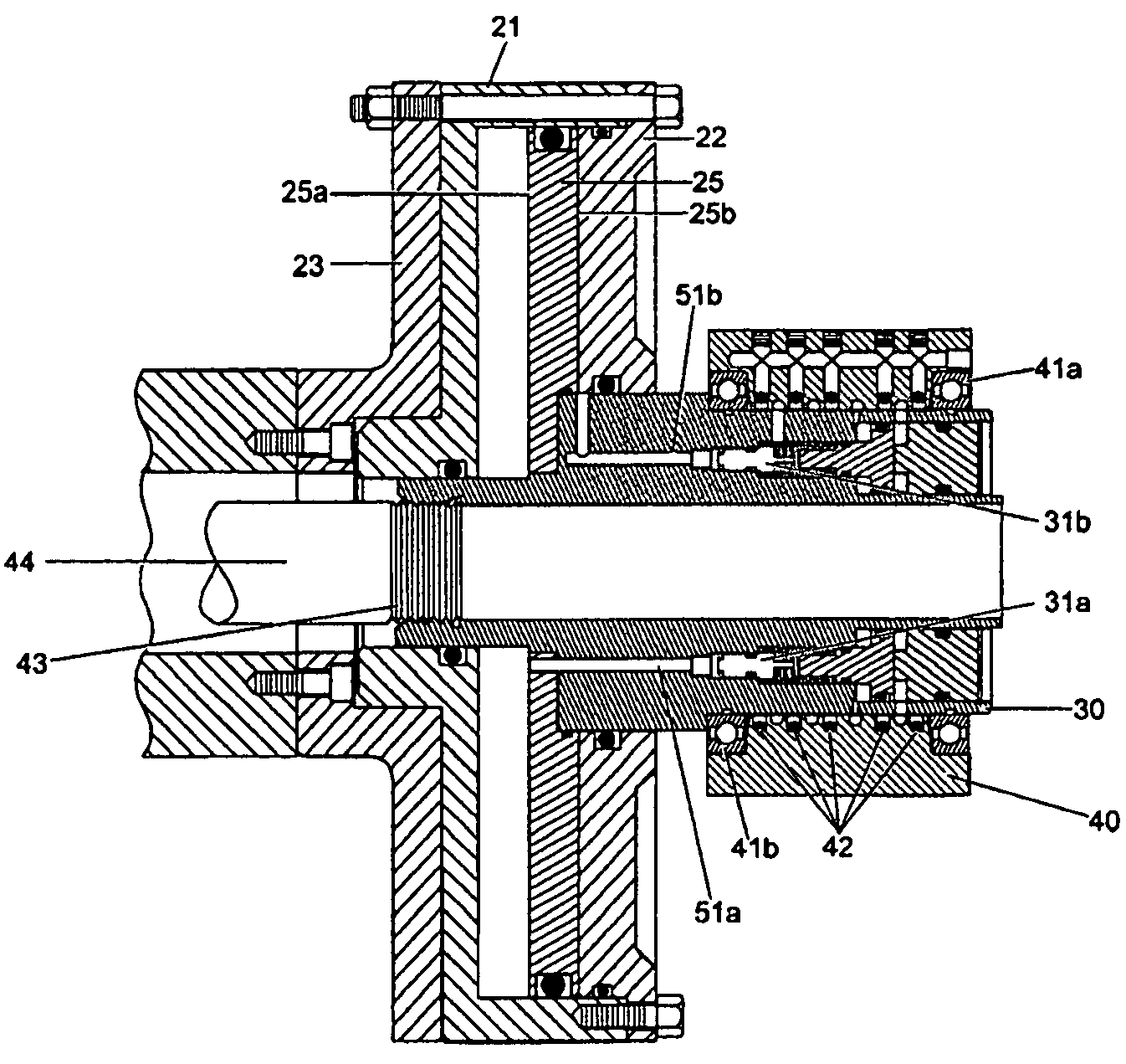
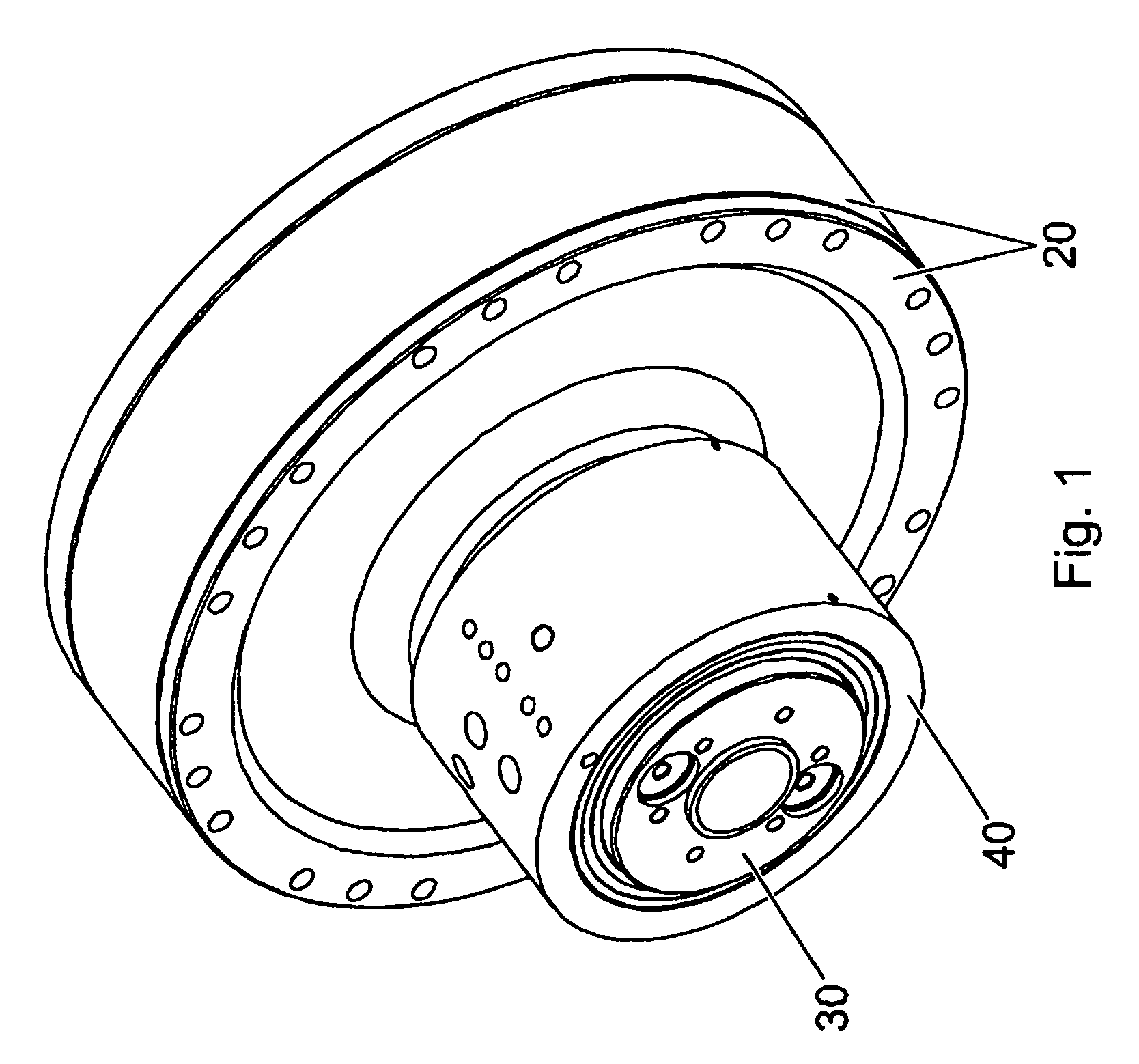
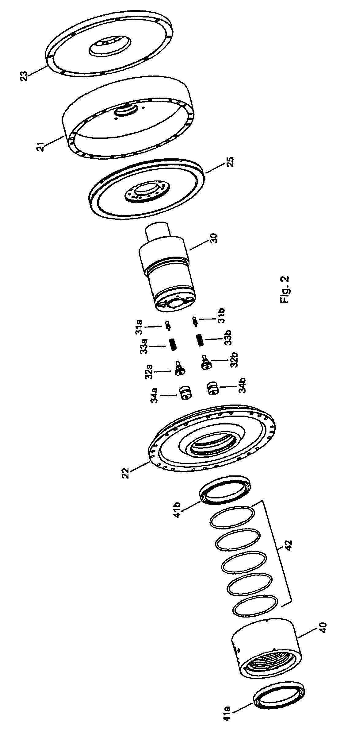
[0022]FIG. 1 is an isometric view of a linear actuator 10 according to one embodiment of the invention. As depicted in FIG. 1, linear actuator 10 includes a cylinder member 20, a rotatable shaft 30 and a pressure delivery body 40. Briefly, cylinder member 20 defines a cavity in which a primary piston (not shown)...


PUM

PropertyMeasurementUnit
pressureaaaaaaaaaa
forceaaaaaaaaaa
pressure lossaaaaaaaaaa

Abstract

A linear actuator for a rotating shaft assembly includes a cylinder and a piston arranged within a cavity defined by the cylinder. Faces of the piston delimit first and second chambers within the cavity. A rotatable shaft fixed to the piston defines a first main passage in fluid communication with the first chamber and a second main passage in fluid communication with the second chamber. A pressure delivery body rotatably fixed to the rotatable shaft defines a first delivery passage in fluid communication with the first main passage and a second delivery passage in fluid communication with the second main passage. A passage isolation system selectively isolates fluid communication between the first delivery passage and the first main passage and fluid communication between the second delivery passage and the second main passage. A pressure limiting system selectively blocks fluid communication through the first and second main passages.

Description

BACKGROUND OF THE INVENTION[0001]The present invention concerns linear actuators, and more particularly linear actuators for use with rotating shaft assemblies.[0002]Linear actuators provide a linear range of motion and force useful in a number of applications. For example, linear actuators are often used to position and / or clamp work pieces in machine tools. Certain applications require the linear actuator to accommodate a rotatable shaft. For example, some lathe machine tools attach a chuck to a rotatable shaft actuated by a linear actuator. Using the linear actuator and chuck, a work piece is positioned and clamped in the lathe machine tool while it is rotated during the machining process. The rotation of the shaft, however, presents challenges to the design and operation of the linear actuator.[0003]Linear actuators are typically operated using either mechanical systems (stepper motors, gears, springs, etc.) or pressurized fluid systems (gas or liquid). Many mechanical systems c...

Claims


Application Information

Patent Timeline
Patent Type & Authority Patents(United States)
IPC IPC(8): F01B31/00B21B31/30
CPCF15B15/149Y10T279/12
Inventor HAAS, GENE F.RYAN, JOHN W.ROCKSVOLD, NICHOLAS M.TANDROW, WILLIAM F.
Owner HAAS AUTOMATION
Why Eureka
Try Eureka