Wheel support bearing assembly with built-in load sensor

a technology of load sensor and bearing assembly, which is applied in the direction of instruments, force/torque/work measurement apparatus, transportation and packaging, etc., can solve the problems of increasing hysteresis of torque output, affecting the sensitivity of load detection, and uneven load acting on the wheels

Active Publication Date: 2009-10-20
NTN CORP
View PDF17 Cites 31 Cited by
  • Summary
  • Abstract
  • Description
  • Claims
  • Application Information

AI Technical Summary

Benefits of technology

[0006]An object of the present invention is intended to solve those problems and to provide a wheel support bearing assembly with a built-in load sensor capable of accurately detecting a load on a wheel without being affected by the connection, for example, the spline connection between the bearing assembly and an outer race of a constant velocity universal joint and also enabling the compact installation of the load sensor on a vehicle.
[0031]Even in the case of this construction, when the load acts, the phase difference can easily be developed between the inner member and the outer race and, therefore, the load detecting sensitivity can be increased.

Problems solved by technology

The automobile traveling safety precaution is hitherto generally taken by detecting the rotational speed of a wheel, but it is not sufficient with only the rotational speed of the wheel and, therefore, it is required to achieve a control for safety purpose with the use of other sensor signals.
Also, even in the case of the uneven live load, the loads acting on the wheels tend to become uneven.
However, no space for installation of the load sensor for detecting the load acting on the respective vehicle wheel is available and, therefore, the attitude control through the detection of the load can hardly be realized.
Once the spline connection loosens, the hysteresis of the torque output increases.
However, in the case of the torque transmission in a reverse direction, the strain acts in a direction in which the twist may lessen, and the torque is not accurately transmitted to the to-be-detected portion of the sensor, resulting in reduction in sensitivity of the sensor and linearity of the sensor output.

Method used


Image

  • Wheel support bearing assembly with built-in load sensor
  • Wheel support bearing assembly with built-in load sensor
  • Wheel support bearing assembly with built-in load sensor

Examples


first embodiment

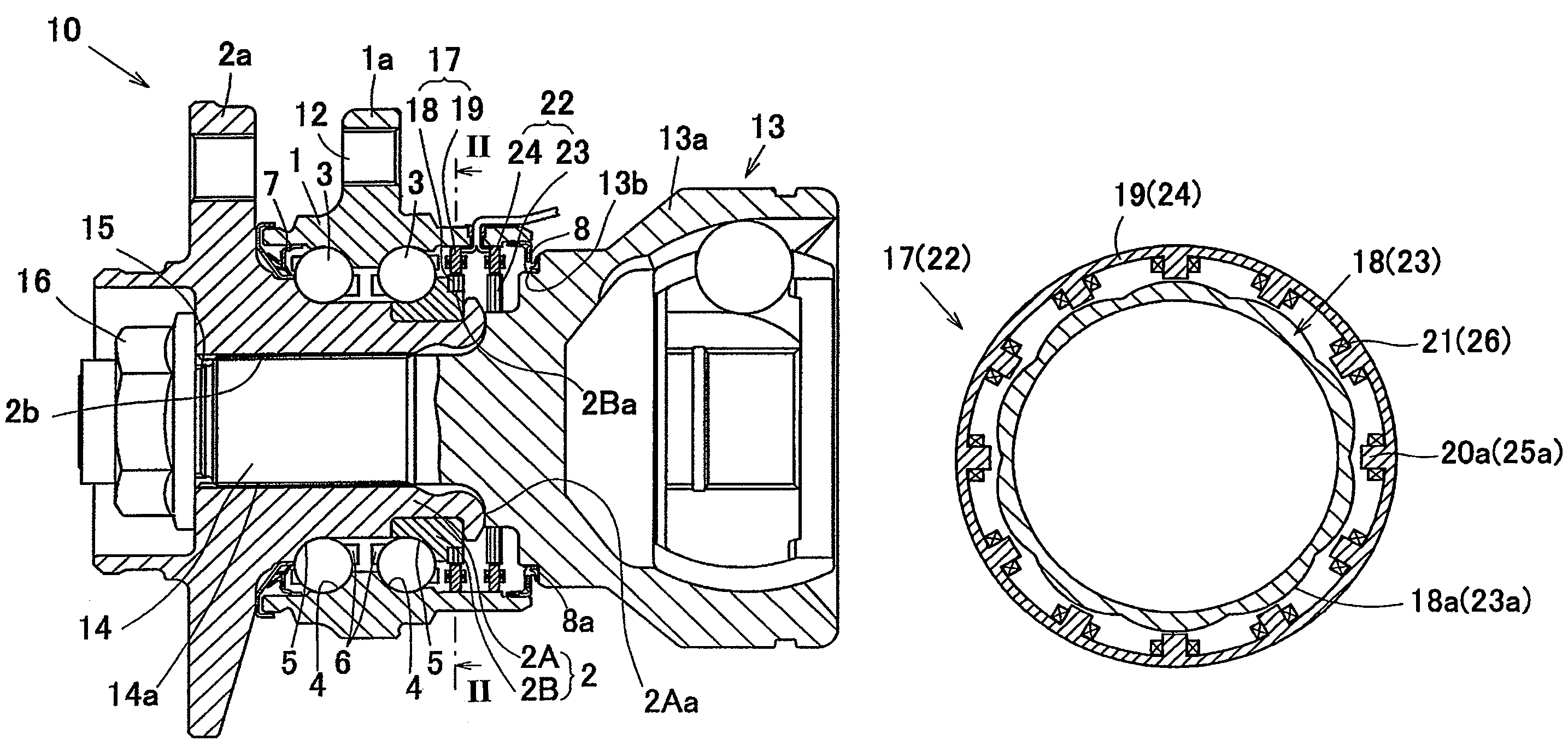
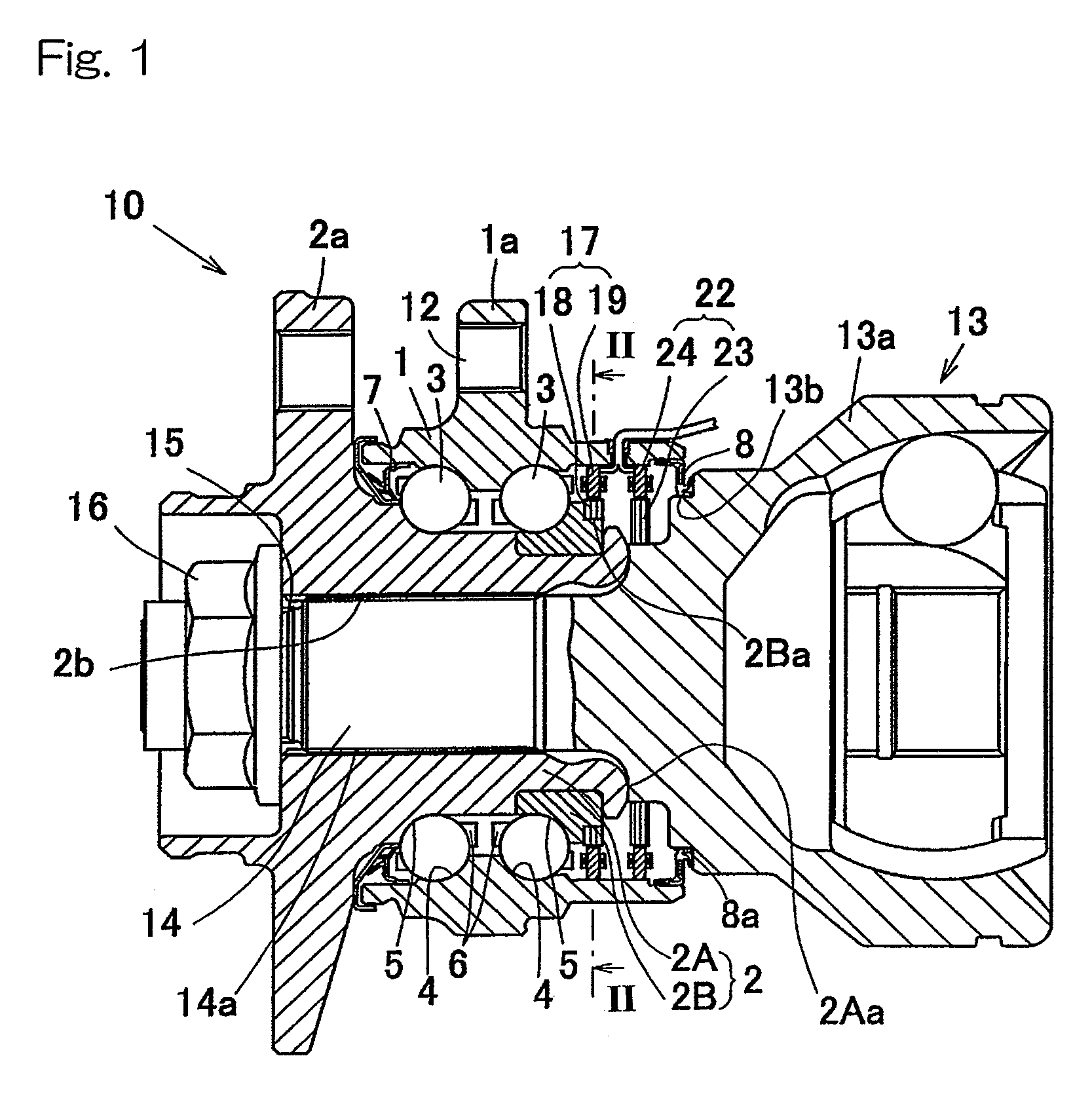
[0052]The first preferred embodiment of the present invention will be described with particular reference to FIGS. 1 to 4. A wheel support bearing assembly with a built-in load sensor is applied to a third-generation wheel support bearing assembly of an inner race rotating type that is used to support a drive wheel. It is to be noted that the terms “inboard” and “outboard” represent the sides facing the inside and the outside, respectively.

[0053]Referring to FIG. 1, the wheel support bearing assembly 10 includes an outer member 1 having an inner peripheral surface formed with double rows of raceway surfaces 4, an inner member 2 having an outer peripheral surface formed with double rows of raceway surfaces 5 confronting those raceway surfaces 4, and double rows of rolling elements 3 interposed between those double rows of the raceway surfaces 4 and 5. This wheel support bearing assembly 10 is a double row angular contact ball bearing. Each of the raceway surfaces 4 and 5 is of an ar...

second embodiment

[0066]A portion of the outer peripheral surface of the outer race 13a shown in FIG. 5A is provided with a to-be-detected part 40 of the second rotational angle detecting sensor 39 adjacent the inboard end face (the staked portion 2Aa in this second embodiment) of the hub axle 2A which contacts the outer peripheral surface of the outer race 13a. A detecting part 41 of the second rotational angle detecting sensor 39 is provided at a portion of the inner peripheral surface of the outer member 1 radially opposed to the to-be-detected part 40. The to-be-detected part 40 and the detecting part 41 altogether form the second rotational angle detecting sensor 39. Even this second rotational angle detecting sensor 39 is of the same construction as the first rotational angle detecting sensor 35. Specifically, as shown in FIG. 6 by the reference numerals depicted along with those of the first rotational angle detecting sensor 35, the to-be-detected part 40 is a magnetic encoder including an ann...

third embodiment

[0081]FIGS. 14 and 15 illustrate a fifth preferred embodiment of the present invention. This wheel support bearing assembly 10 with the built-in load sensor is such that in place of the rings 52 and 52 forming the pulsar ring in the third embodiment shown in and described with reference to FIGS. 9 to 11, a plurality of indentations 68 and a plurality of indentations 69 are provided on the respective outer peripheral surfaces of the outer race 13a and the inner race 2B adjacent a boundary between the outer race 13a and the inner race 2B so that the indentations 68 and the indentations 69 confront with each other in contact relation, as shown in a fragmentary enlarged view in FIG. 15. The indentations 68 and the indentations 69 are spaced equally in circumferential directions of the outer race 13a and the inner race 2B, respectively. The inner race 2B and the outer race 13a have the same outer diameter adjacent the boundary.

[0082]The indentations 68 and 69 are so arranged that they ar...


PUM


Abstract

A wheel support bearing assembly comprises a stationary outer member and a rotatable inner member. The to-be-detected parts of angle detection sensors are fixed to the inner member and an outer race of a constant velocity joint connected to the inner member, respectively. Detecting parts of the angle detection sensors are fixed to the outer member in face-to-face relation with the to-be-detected parts. The bearing assembly also includes a load conversion unit detecting a relative angular difference between the inner member and the constant velocity universal joint by comparing the detection signals from the detecting parts to detect the load acting on the bearing assembly.

Description

FIELD OF THE INVENTION[0001]The present invention relates to a wheel support bearing assembly with a built-in load sensor for detecting a load acting on a bearing portion of the wheel.BACKGROUND ART[0002]Hitherto, a wheel support bearing assembly having a sensor for detecting the rotational speed of each of wheels for safe travel of an automotive vehicle is known. In such a wheel support bearing assembly, it is suggested to install a sensor such as a temperature sensor, torque sensor or a vibration sensor for detecting other information useful for the operation of an automotive vehicle than the rotational speed. (See, for example, the Japanese Laid-open Patent Publications No. 2002-340922 (Patent Document 1) and No. 2003-207402 (Patent Document 2).) In the wheel support bearing assembly disclosed in the Patent Document 1, a to-be-detected part of a rotation sensor is disposed between two rows of raceway surfaces defined on an outer peripheral surface of a rotatable inner member and,...

Claims


Application Information

Patent Timeline
Patent Type & Authority Patents(United States)
IPC IPC(8): F16C41/04F16C19/08G01P3/42
CPCF16C19/522G01L5/0023F16C19/186F16C2326/02F16C41/007
Inventor KOIKE, TAKASHIISHIKAWA, TOMOMI
Owner NTN CORP
Why Eureka
Try Eureka