
Bioreactor for growing cell or tissue cultures

a technology for growing cells and tissue, applied in the field of bioreactors for growing cells or tissue cultures, can solve the problems of not providing a constant and regulatory supply of nutrition and removal, fibrous scarring of tissue, and different functions from naturally grown cells, so as to facilitate cell or tissue culture growth and facilitate cell and tissue growth

Active Publication Date: 2009-10-20
SINGAPORE POLYTECHNIC +1
View PDF20 Cites 29 Cited by
  • Summary
  • Abstract
  • Description
  • Claims
  • Application Information

AI Technical Summary

Benefits of technology

The patent describes a bioreactor that can grow cell or tissue cultures in a controlled environment. The bioreactor has a chamber with a detector to detect changes in metabolites associated with cell growth. The chamber can rotate at different speeds and at different angles to create a unique growth environment. The bioreactor can also maintain pressure within the chamber and can continuously rotate the chamber. The technical effects of this invention include improved control over cell growth and the ability to create a more complex growth environment for cells and tissues.

Problems solved by technology

However, incomplete repair of the tissue may result when the defect is large, thereby resulting in fibrous scarring of the tissue.
The fibrous scarring often possesses physical and mechanical properties that are inferior to that of non-scarred tissue.
Difficulties have arisen with known bioreactors in that they have not provided a constant and regulatory supply of nutrition and removal of metabolic byproducts.
Although cells grown in culture dishes multiply quite well, they tend to loose their differentiation status and are therefore functionally different from naturally grown cells.
A disadvantage with this procedure is that skin is taken from non-defect area of the patient's skin and some scarring may remain at the graft site.
Furthermore, in circumstances where a wound extends over a wide area, it is difficult to carry out autologous split-thickness skin grafting.
Although the growth of cells in two dimensions is suitable for studying cells in culture, it lacks the cell-cell and cell-matrix interactions that are characteristic of whole tissue in vivo.
Another disadvantage with some bioreactors for growing cell tissues is that they are designed to operate in batch or semi-batch mode.

Method used


Image

  • Bioreactor for growing cell or tissue cultures
  • Bioreactor for growing cell or tissue cultures
  • Bioreactor for growing cell or tissue cultures

Examples


embodiment 1

Dual Axis Bioreactor

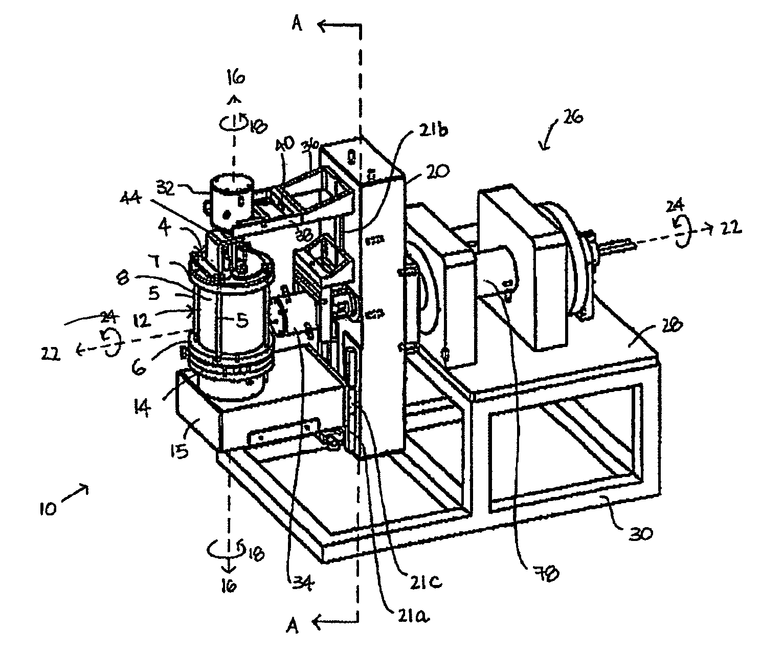
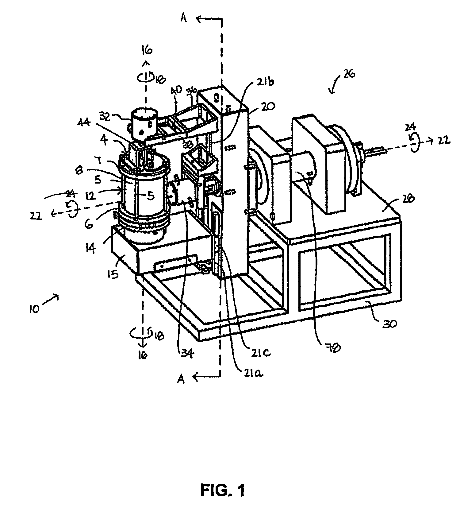
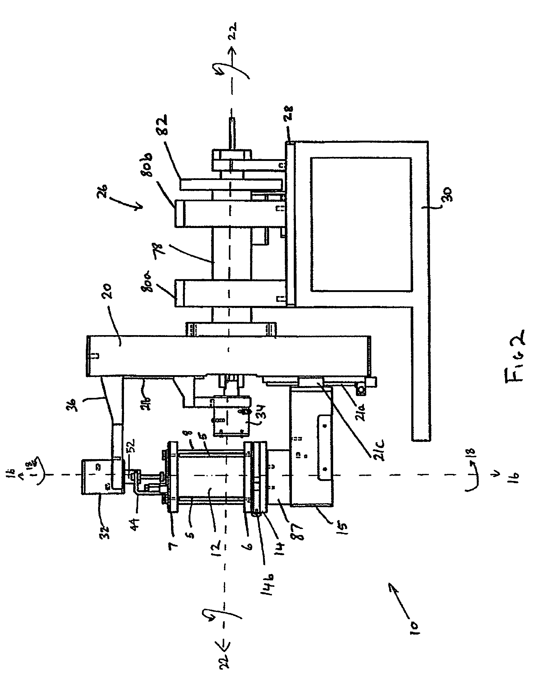
[0172]FIG. 1 shows a perspective view of a first preferred embodiment of a dual axis bioreactor 10 that is used to grow cell or tissue cultures. The bioreactor 10 includes a chamber 12 for containing a cell or tissue culture and a culture medium for growing cell or tissue cultures in use. The bioreactor 10 also includes a drive mechanism 26 for rotating the chamber 12 at a first speed about a first vertical axis 16 and at a second speed about a second horizontal axis 22. The horizontal axis is normal relative to the vertical axis. As will be described further below, in use, the magnitude of the first speed and the second speed are independently variable of each other to thereby grow a cell or tissue culture within the chamber.

[0173]Referring to FIGS. 1, 2, 2a, 3, the chamber 12 may be provided with a three-dimensional matrix (not shown) when growing three-dimensional cell or tissue cultures as will be described further below. The chamber 12 includes a glass tube ...

embodiment 2

Dual Axis Bioreactor with Spherical Chamber

[0238]As an alternative to the cylindrical chamber 12, the dual axis bioreactor 10 of embodiment 1 can be replaced with a spherical-shaped chamber 512 shown in FIG. 39. The spherical chamber 512 comprises of a spherical cavity 510. The spherical cavity 510, in use, contains a cell or tissue culture medium, scaffold for cell or tissue culture and cell or tissue of interest. On the outer surface the spherical cavity 510, there are provided hooks (511a, 511b, 511c and 511d) for fixing the cylindrical chamber to the L-shaped bracket 20. The spherical chamber 512 is fixed to the rotary plate 14 by means of cylindrical rods (5a, 5b, 5c and 5d) which respectively extend from the rotary plate to the hooks (511a, 511b, 511c and 511d).

[0239]The spherical chamber 512 is also provided with a conduit 550 that extends from the cavity 510 up to a bottom chamber clamp plate 509. The bottom chamber clamp plate 509 is capable of being fixed to a top chamber ...

embodiment 3

Omni-Directional Rotary Bioreactor

[0245]Referring now to FIG. 35 there is shown a perspective view of another embodiment of a bioreactor for growing cells and tissue cultures, here called an “omni-directional rotary bioreactor 318”. The bioreactor 318 includes a chamber 302 for containing a cell or tissue culture and a culture medium for growing cell or tissue cultures in use. The bioreactor 318 also includes a rotary wheel in the form of wheel 314 (shown in FIG. 36b) for rotating the chamber 302 at a first speed about a first axis 319. The bioreactor 318 also includes a second rotary wheel in the form of wheel 315 for rotating the chamber at a second speed about a second axis 320. The bioreactor 318 also includes a third rotary wheel in the form of wheel 311 at a third speed about a third axis 321. The axes 319, 320 normal relative to each other and both axes are normal relative to the third axis 321. As will be described further below, in use, the magnitude of the first speed, sec...


PUM

PropertyMeasurementUnit
angleaaaaaaaaaa
angleaaaaaaaaaa
rotationaaaaaaaaaa

Abstract

The invention relates to a bioreactor comprising a chamber for containing cells or tissue cultures within a culture medium. The bioreactor also comprises a detector capable of detecting a change in one or more metabolites associated with growth of the cell or tissue cultures within the chamber and a chamber drive capable of rotating the chamber at a first speed about a first axis and a second speed about a second axis, the second axis being disposed at an angle relative to the first axis. In use, the magnitude of the first speed and the second speed are independently variable of each other.

Description

CROSS REFERENCE TO RELATED APPLICATIONS[0001]This application is a continuation-in-part of application Ser. No. 10 / 774,360, filed Feb. 6, 2004, which claims the benefit of U.S. Provisional Application No. 60 / 445,252, filed Feb. 6, 2003. This application also claims the benefit of U.S. Provisional Application No. 60 / 569,484, filed May 7, 2004. All of these applications are incorporated by reference hereinto.TECHNICAL FIELD[0002]The present invention generally relates to a bioreactor for growing cell or tissue cultures.BACKGROUND OF THE INVENTION[0003]Defects in tissues resulting from disease or trauma have previously been healed through the regenerative process of wound healing. However, incomplete repair of the tissue may result when the defect is large, thereby resulting in fibrous scarring of the tissue. The fibrous scarring often possesses physical and mechanical properties that are inferior to that of non-scarred tissue.[0004]Dramatic advances in the fields of biochemistry, cell...

Claims


Application Information

Patent Timeline
Patent Type & Authority Patents(United States)
IPC IPC(8): C12M1/00
CPCC12M21/08C12M41/32C12M27/10
Inventor HUTMACHER, DIETMAR W.TEOH, SWEE HINRANAWAKE, MANOJACHONG, WOON SHINTING, KENG SOONCHUA, KAY CHIANGMYINT, THANPUAH, CHUM MOKFOO, TOON TIENSCHANTZ, JAN-THORSTEN
Owner SINGAPORE POLYTECHNIC
Learn More