Magnet coil system with active drift compensation for two independent current paths

a technology of active drift compensation and magnet coil, which is applied in the direction of superconducting magnets/coils, using reradiation, magnetic materials, etc., can solve the problems of large field drift, hts-lts, and produce field drift, so as to facilitate loading with external current sources and reduce current density in one area of the winding pack

Inactive Publication Date: 2009-10-20
BRUKER SWITZERLAND AG
View PDF7 Cites 2 Cited by
  • Summary
  • Abstract
  • Description
  • Claims
  • Application Information

AI Technical Summary

Benefits of technology

[0021]When the H2 gradient of the corresponding partial magnetic field of a partial coil is smaller than 0.1 Gauss / (cm2A) as described above, the H2 gradient of the overall system can be corrected with room temperature shims. An assumed typical current difference of 10 A results in a H2 gradient of at most 1 Gauss / cm2, which corresponds approximately to half the maximum possible current in a typical room temperature shim system for the Z2 shim. The H2 gradient of a partial coil can e.g. be reduced by using a notch structure in the winding packet. Towards this end, the current density in one area in the center of the winding packet can be reduced by providing less current-carrying windings or none at all in this area.
[0022]One or more of the partial coils are advantageously largely inductively decoupled from the other partial coils. Loading with the external current source is facilitated, since the partial coils can be successively charged with the corresponding current without excessively influencing the currents in the other partial coils. On the other hand, in case of a quench of one partial coil without decoupling, dangerously high currents could inductively build up in other partial coils, which could even destroy these partial coils.
[0025]In one advantageous further development of this embodiment, the subsections are at least partially disposed at different radii. The distribution of subsections of a partial coil at different radii can be used to reduce the H2 gradient of a partial coil by positioning the subsections in such a fashion that the H2 gradients of the coil sections partially compensate each other.

Problems solved by technology

When an HTS coil is connected in series with an LTS coil, the connections between HTS and LTS (HTS-LTS joints) are often problematic and produce a field drift.
Even minor problems with wires or superconducting connections produce a large field drift, in particular, since the HTS coil substantially contributes to the field.
This involves great expense, requires a large amount of space in the cryostat and is also susceptible to failure due to the increased complexity.
Both flux pumps would then have to be controlled and field control would be complex.
In particular, it would be difficult to determine which partial coil produces which part of the field loss.
The use of two flux pumps would, however, most likely result in uncontrolled current shifts from one electric circuit to the other.
In order to prevent this, the currents of the partial coils would have to be measured, which is relatively demanding, e.g. using Hall probes inside a measuring winding slightly outside of the magnet.
It is, however, doubtful whether this measurement is sufficiently precise.
In total, this possibility of drift compensation does not seem to be practicable.

Method used


Image

  • Magnet coil system with active drift compensation for two independent current paths
  • Magnet coil system with active drift compensation for two independent current paths
  • Magnet coil system with active drift compensation for two independent current paths

Examples


Embodiment Construction

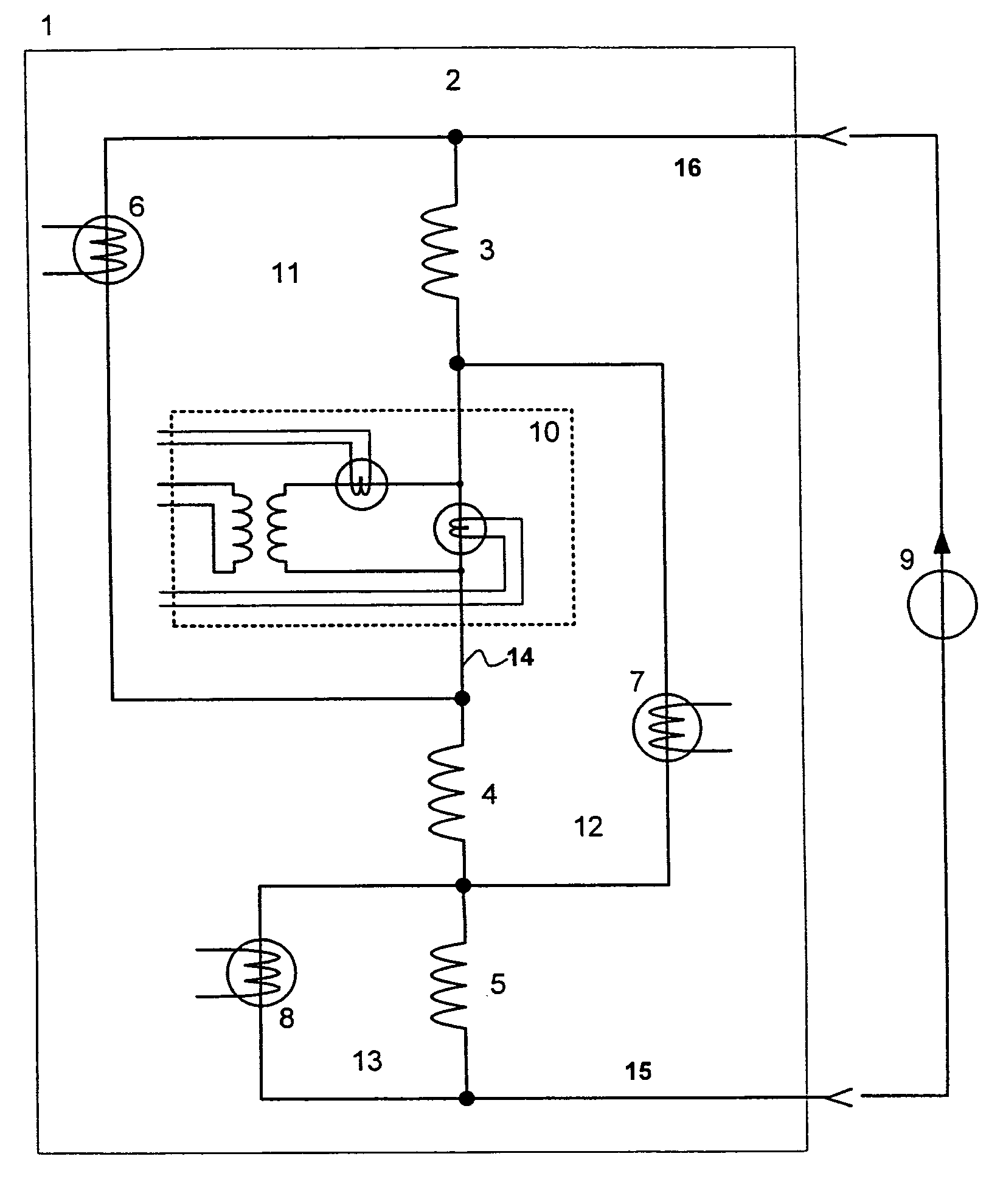
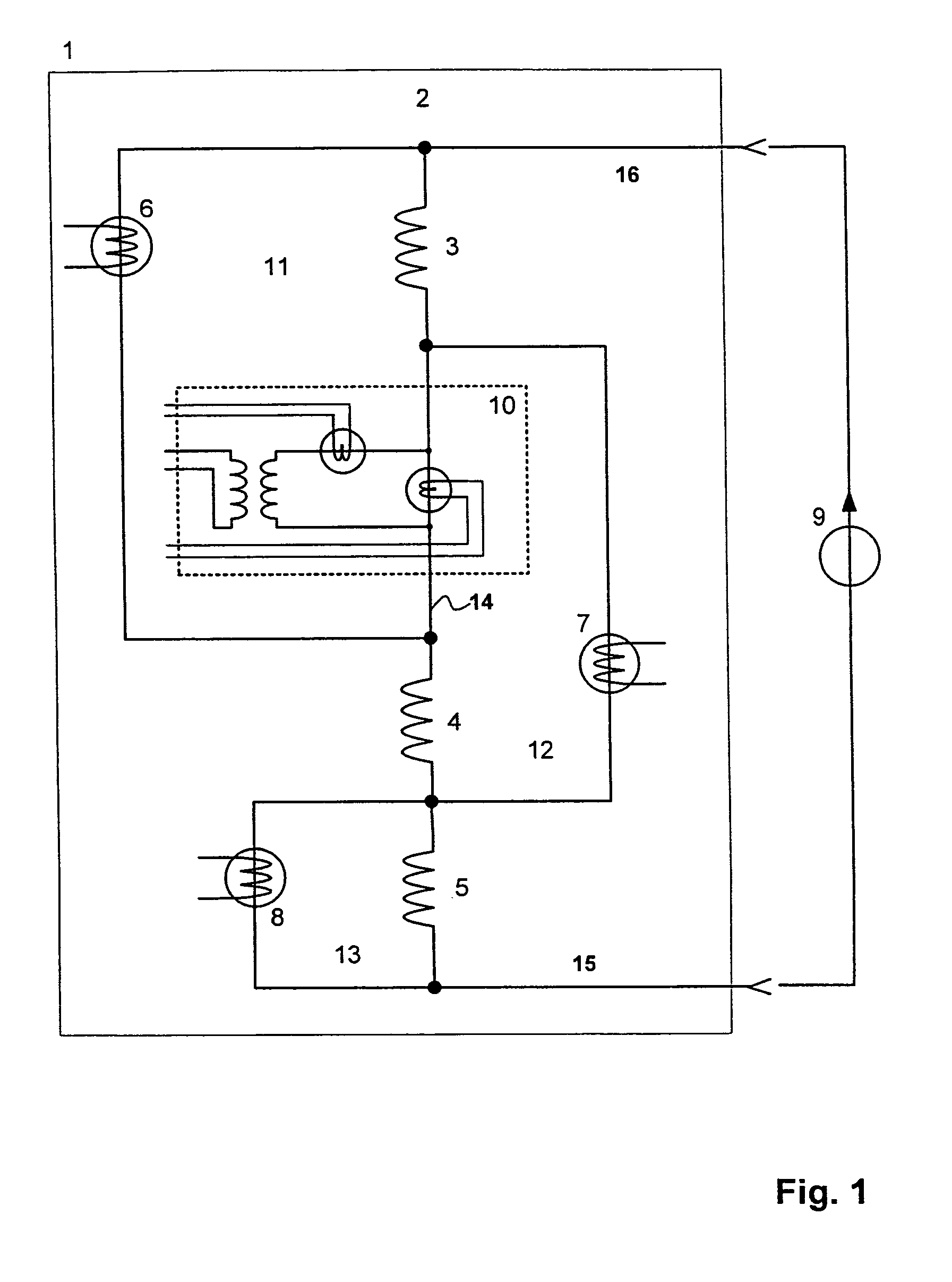
[0033]FIG. 1 shows an inventive magnet coil system 2 that is disposed in a cryogenic chamber 1. The magnet coil system 2 comprises three superconducting partial coils 3, 4, 5 which are connected in series. Each partial coil 3, 4, 5 is bridged with a superconducting switch 6, 7, 8. The partial coils 3, 4, 5 form independent electric loops 11, 12, 13 when the superconducting switches 6, 7, 8 are closed. The magnet coil system 2 is at least partially superconducting, i.e. it may comprise resistive parts which result in a drift. These resistive parts may occur e.g. when the superconducting partial coils are operated close to their critical current. It is, however, also possible that the joints used in the magnet coil system 2 are defective or resistively soldered, and therefore cause a drift.

[0034]A power supply 9 is connected to the magnet coil system 2 via a pair of current supply lines 15, 16 for charging the magnet coil system 2. The charging process of the partial coils bridged by ...


PUM

PropertyMeasurementUnit
voltageaaaaaaaaaa
voltageaaaaaaaaaa
NMR proton frequencyaaaaaaaaaa

Abstract

A magnet coil system (2) which is at least partially superconducting at a cryogenic temperature, comprising at least two partial coils (3, 4, 5) which are connected in series and are each bridged by a superconducting switch (6, 7, 8), such that the partial coils form independent electric loops (11, 12, 13) when the superconducting switches (6, 7, 8) are closed, is characterized in that two electric loops (11, 12) have a common section and a flux pump (10) is provided which is circuited in the common section (14) of the electric loops (11, 12) of two partial coils (3, 4), wherein the sum of the currents of the two partial coils (3, 4) flows through the flux pump (10) in the operating state. In this fashion, the drifts of two independent electric loops can be compensated for with a few devices.

Description

[0001]This application claims Paris Convention priority of DE 10 2007 006 324.7 filed Feb. 8, 2007 the complete disclosure of which is hereby incorporated by reference.BACKGROUND OF THE INVENTION[0002]The invention concerns a magnet coil system that is at least partially superconducting at a cryogenic temperature, comprising at least two serially connected partial coils which are each bridged by a superconducting switch, such that the partial coils form independent current loops when the superconducting switches are closed.[0003]A magnet coil system of this type is disclosed in US 2006 / 0066429 A1.[0004]By connecting several superconducting coils in series, wherein each coil is bridged by a superconducting switch, the coils can be sequentially charged with individual currents via one single current source and one single pair of current supply lines. When the coils are magnetically decoupled from each other, each coil can be directly charged with its current. This principle is normall...

Claims


Application Information

Patent Timeline
Patent Type & Authority Patents(United States)
IPC IPC(8): H01F6/00
CPCG01R33/3815H01F6/008H01F6/005Y10S505/851
Inventor SPREITER, ROLFVONLANTHEN, PATRIK
Owner BRUKER SWITZERLAND AG
Why Eureka
Try Eureka