Regenerative turbine blade and vane cooling for a tip turbine engine

a tip turbine engine and turbine blade technology, applied in the direction of liquid fuel engines, machines/engines, efficient propulsion technologies, etc., can solve the problems of relative complexity of the engine structure of considerable longitudinal length, inefficient, and inability to reduce the efficiency of the engine, so as to minimize the effect of engine operation efficiency

Inactive Publication Date: 2009-10-27
RAYTHEON TECH CORP
View PDF147 Cites 18 Cited by
  • Summary
  • Abstract
  • Description
  • Claims
  • Application Information

AI Technical Summary

Benefits of technology

[0011]The diffuser includes a multitude of diffuser passages which turn and diffuse the airflow from a radial core airflow passage toward an axial airflow direction. A multitude of diffuser aspiration passages are in communication with the diffuser passages and through the diffuser surface. Diffuser aspiration passages communicate with the diffuser passages at a location which reduces separation of the airflow as the airflow is turned from the radial core airflow passage toward an axial airflow direction through airflow aspiration at the potentially turbulent locations.
[0012]Each of the multitude of turbine blades defines a turbine blade passage. The turbine blade passages bleed air from the diffuser to provide for regenerative cooling. Regenerative cooling airflow is communicated from the radial core airflow passage through the diffuser passages, through the diffuser aspiration passages and into the turbine blade passages. The regenerative cooling airflow receives thermal energy from the turbine blades and increases the centrifugal compression within the turbine while transferring the increased temperature cooling airflow into the annular combustor to increase the efficiency thereof through regeneration.
[0014]The present invention therefore provides a turbine for a fan-turbine rotor assembly of a tip turbine engine which provides regenerative cooling airflow while minimizing the effect on engine operating efficiency.

Problems solved by technology

The axial flow relationship results in a relatively complicated elongated engine structure of considerable longitudinal length relative to the engine diameter.
This elongated shape may complicate or prevent packaging of the engine into particular applications.
Integrating the turbine onto the tips of the hollow bypass fan blades provides an engine design challenge.
This may be somewhat inefficient from a thermal standpoint which may reduce the engine operating efficiency.

Method used


Image

  • Regenerative turbine blade and vane cooling for a tip turbine engine
  • Regenerative turbine blade and vane cooling for a tip turbine engine
  • Regenerative turbine blade and vane cooling for a tip turbine engine

Examples


Embodiment Construction

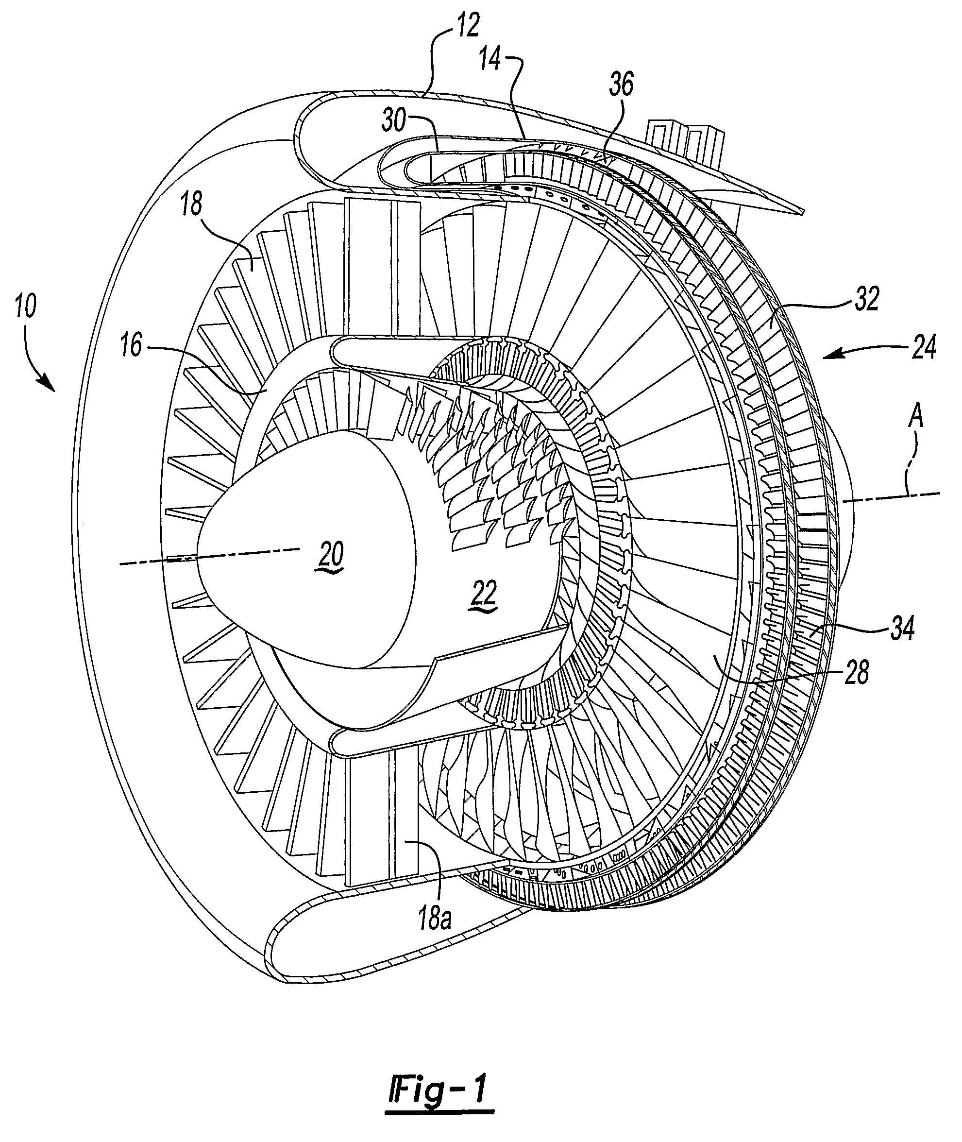
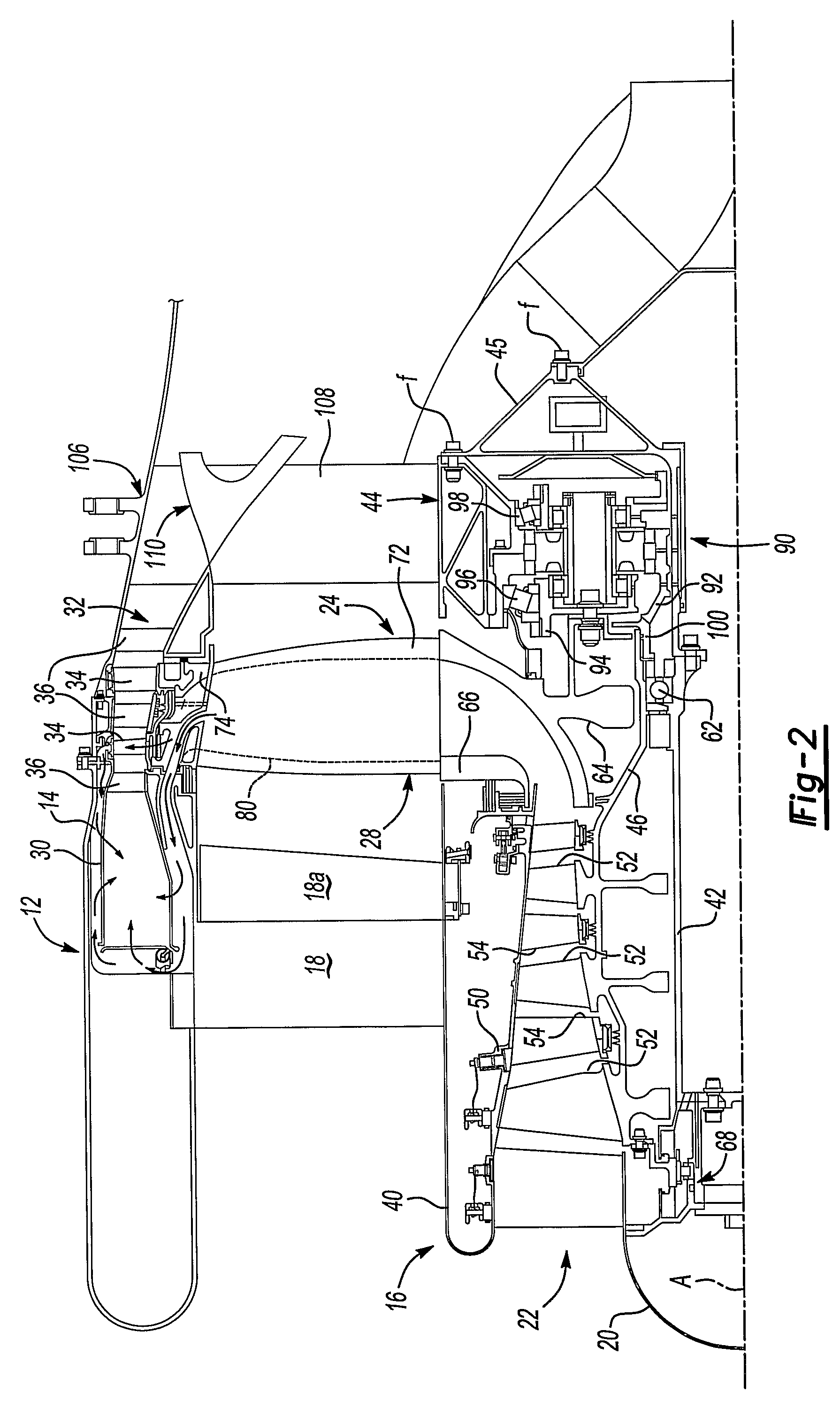
[0039]FIG. 1 illustrates a general perspective partial sectional view of one embodiment of a tip turbine engine type gas turbine engine 10. The engine 10 includes an outer nacelle 12, a rotationally fixed static outer support structure 14 and a rotationally fixed static inner support structure 16. The engine 10 can also include a multitude of fan inlet guide vanes 18 mounted between the static outer support structure 14 and the static inner support structure 16. Each inlet guide vane 18 could include a separate variable trailing edge 18A which may be selectively articulated relative to the fixed inlet guide vane 18.

[0040]The engine 10 can have a nose cone 20 located along the engine centerline A to smoothly direct airflow near the engine centerline A radially outwardly and into the engine 10. The airflow enters the engine 10 through an axial compressor 22 (“core” or “primary” airflow) or through a fan-turbine rotor assembly 24 (“bypass” or “secondary” airflow). The axial compressor ...


PUM


Abstract

A fan-turbine rotor assembly (24) includes a multitude of turbine blades (34) which each define a turbine blade passage which bleed air from a diffuser section (74) to provide for regenerative cooling. Regenerative cooling airflow is communicated from the radial core airflow passage (80) through the diffuser passages (144), through diffuser aspiration passages (146A, 146B) and into the turbine blade passages (150a). The regenerative cooling airflow exits from the turbine blade passage (150a) and transfers received thermal energy into an annular combustor (30). The received thermal energy is recovered at the highest temperature in the cycle.

Description

[0001]This invention was made with government support under Contract No.: F33657-03-C-2044. The government therefore has certain rights in this invention.BACKGROUND OF THE INVENTION[0002]The present invention relates to a gas turbine engine, and more particularly to airflow within a tip turbine engine to cool various sections thereof.[0003]An aircraft gas turbine engine of the conventional turbofan type generally includes a forward bypass fan a compressor, a combustor, and an aft turbine all located along a common longitudinal axis. A compressor and a turbine of the engine are interconnected by a shaft. The compressor is rotatably driven to compress air entering the combustor to a relatively high pressure. This pressurized air is then mixed with fuel in a combustor and ignited to form a high energy gas stream. The gas stream flows axially aft to rotatably drive the turbine which rotatably drives the compressor through the shaft. The gas stream is also responsible for rotating the by...

Claims


Application Information

Patent Timeline
Patent Type & Authority Patents(United States)
IPC IPC(8): F02K3/02
CPCF01D5/022F01D5/187F02K3/068F02C3/073F05D2260/205Y02T50/676Y02T50/60
Inventor SUCIU, GABRIEL L.NORRIS, JAMES W.NORDEEN, CRAIG A.
Owner RAYTHEON TECH CORP
Why Eureka
Try Eureka