Eureka AIR delivers breakthrough ideas for toughest innovation challenges, trusted by R&D personnel around the world.

Composite-wing aircraft with tail rotor

A composite and aircraft technology, applied in the field of aircraft, can solve the problems of inconvenient ultra-low speed or hovering flight, difficulty in short-distance take-off and landing, and low efficiency

Inactive Publication Date: 2016-02-03
FOSHAN SHENFENG AVIATION SCI & TECH
View PDF4 Cites 1 Cited by
  • Summary
  • Abstract
  • Description
  • Claims
  • Application Information

AI Technical Summary

Problems solved by technology

[0002] Traditional aircraft need a runway to take off and land, cannot take off and land vertically, and are not convenient for ultra-low speed or hovering flight, and it is also difficult to take off and land in a short distance
Traditional helicopters have high energy consumption, low efficiency, low safety and stability

Method used


Image

  • Composite-wing aircraft with tail rotor
  • Composite-wing aircraft with tail rotor

Examples


Embodiment Construction

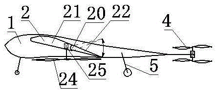
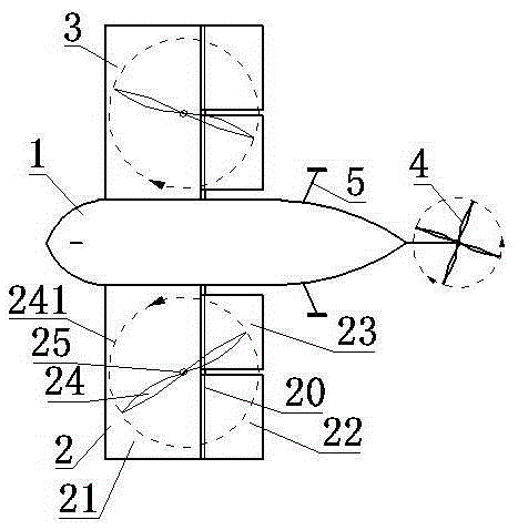
[0009] Now in conjunction with accompanying drawing, the present invention is described in detail: a kind of composite wing aircraft with tail rotor, comprises fuselage 1, left composite wing 2, right composite wing 3, coaxial double-rotor tail rotor 4 and landing gear 5 . The fuselage 1 is equipped with a control system and airborne equipment. The left compound wing 2 and the right compound wing 3 have the same structure, and they are symmetrically installed on the left and right sides of the fuselage 1. The coaxial dual-rotor tail rotor 4 is located at the tail of the fuselage 1. The coaxial dual-rotor tail rotor 4 includes two electric propellers with the same parameters and opposite directions. Online, they are controlled independently. Landing gear 5 adopts wheel structure. The concrete structure of left compound wing 2 is: left compound wing 2 comprises wing shaft 20, front wing 21, rear outer wing 22, rear inner wing 23, rotor 24 and engine 25. Engine 25 provides po...


PUM


Abstract

The invention relates to a composite-wing aircraft with a tail rotor, which belongs to the technical field of aircrafts. The composite-wing aircraft with the tail rotor comprises an aircraft body, a left composite wing, a right composite wing, a coaxial double-blade tail rotor and a landing gear. An operating system and airborne equipment are mounted in the aircraft body. The left composite wing and the right composite wing have same structures and are symmetrically mounted on the left and right sides of the aircraft body. The coaxial double-blade tail rotor comprises two electric propellers with same parameters and reverse rotation directions; and the two electric propellers are horizontally arranged with one under the other and independently controlled. The landing gear adopts a wheel type structure or a skid and wheel combined structure. The left composite wing comprises a wing shaft, a front wing, a rear outer wing, a rear inner wing, a rotor and an engine. The rear outer wing and the rear inner wing can both swing around the wing shaft. The rotating plane of the rotor is in a horizontal position. Flow fields of the upper and lower surfaces of the wing can be improved during the rotating of the rotor; therefore, downwash airflow is increased and airflow separation of the upper surface of the wing is delayed. The composite-wing aircraft with the tail rotor, provided by the invention, has the advantages of safety, high efficiency and good flexibility.

Description

technical field [0001] A composite wing aircraft with a tail rotor belongs to the technical field of aircraft, and in particular relates to a composite wing aircraft. Background technique [0002] Traditional aircraft need a runway to take off and land, and cannot take off and land vertically. Traditional helicopters have high energy consumption, low efficiency, and low safety and stability. Contents of the invention [0003] The purpose of the present invention is to overcome the above-mentioned deficiency of traditional aircraft and helicopter, invent a kind of compound wing aircraft with tail rotor that is efficient, safe and stable for short-distance take-off and landing and vertical take-off and landing. [0004] A compound wing aircraft with a tail rotor comprises a fuselage, a left compound wing, a right compound wing, a coaxial twin-rotor tail rotor and a landing gear. The fuselage is equipped with a control system and airborne equipment. The left composite wing...

Claims


Application Information

Patent Timeline
IPC IPC(8): B64C27/06B64C27/22B64C27/24B64C9/00B64C5/00
Inventor 王志成
Owner FOSHAN SHENFENG AVIATION SCI & TECH
Why Eureka
Eureka Blog
Learn More