Flow-increasing aero-engine with heat and momentum recovery function
A technology for aero-engines and engines, which is applied to machines/engines, mechanical equipment, gas turbines, etc., and can solve problems such as difficulty in taking into account performance
- Summary
- Abstract
- Description
- Claims
- Application Information
AI Technical Summary
Problems solved by technology
Method used
Image
Examples
Embodiment 1
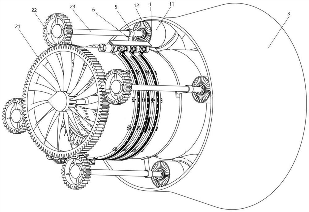
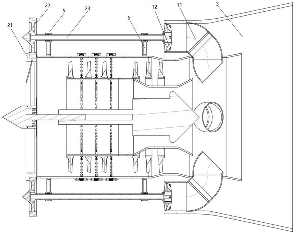
[0032] Such as figure 1 with figure 2 As shown, a flow-increasing aero-engine with heat and momentum recovery functions includes a flow-increasing mechanism 1 connected to the engine tail nozzle and a transmission mechanism 2 connected to the engine fan, and the transmission mechanism 2 is connected with the flow-increasing mechanism 1 for use Guide the outside air to the engine exhaust nozzle in the transmission flow increasing mechanism 1;
[0033] Further, the number of the transmission mechanism 2 and the flow increasing mechanism 1 is multiple, and the plurality of transmission mechanisms 2 and the flow increasing mechanism 1 are arranged on the outside of the engine at an equal distance in a ring, and the number of the flow increasing mechanism 1 and the transmission mechanism 2 can be adjusted. The setting can change the air flow into the tail of the turbine;
[0034] The flow-increasing mechanism 1 includes a flow-increasing duct 11 and a flow-increasing fan 12. The...
Embodiment 2
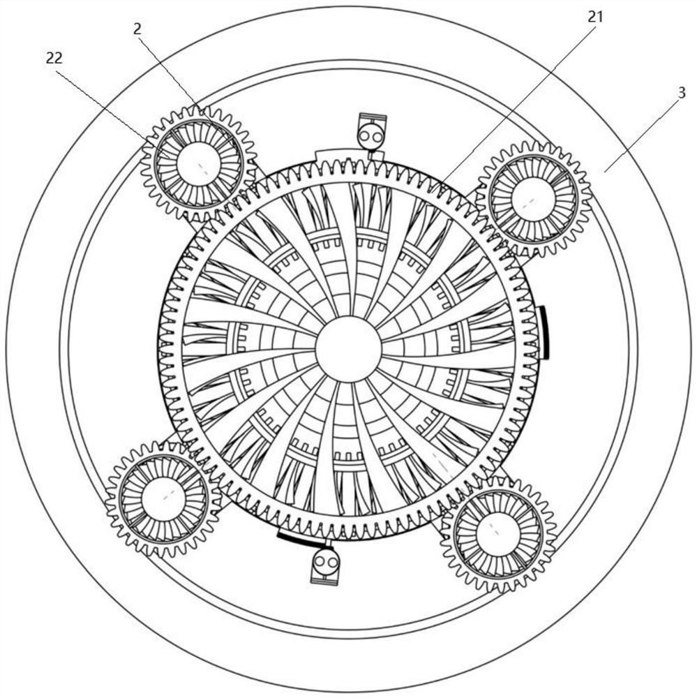
[0038] Such as figure 1 , figure 2 with image 3 As shown, a flow-increasing aero-engine with heat and momentum recovery functions includes a flow-increasing mechanism 1 connected to the engine tail nozzle and a transmission mechanism 2 connected to the engine fan, and the transmission mechanism 2 is connected with the flow-increasing mechanism 1 for use Guide the outside air to the engine exhaust nozzle in the transmission flow increasing mechanism 1.
[0039] The number of the transmission mechanism 2 and the flow increasing mechanism 1 is multiple, and the plurality of transmission mechanisms 2 and the flow increasing mechanism 1 are arranged on the outside of the engine in a ring and equidistant. By setting the number of the flow increasing mechanism 1 and the transmission mechanism 2, The air flow into the tail of the turbine can be varied.
[0040] The flow-increasing mechanism 1 includes a flow-increasing duct 11 and a flow-increasing fan 12. The flow-increasing duc...
Embodiment 3
[0044] Such as figure 1 , figure 2 , image 3 with Figure 4 As shown, a flow-increasing aero-engine with heat and momentum recovery functions includes a flow-increasing mechanism 1 connected to the engine tail nozzle and a transmission mechanism 2 connected to the engine fan, and the transmission mechanism 2 is connected with the flow-increasing mechanism 1 for use Guide the outside air to the engine exhaust nozzle in the transmission flow increasing mechanism 1.
[0045]Further, the number of the transmission mechanism 2 and the flow increasing mechanism 1 is multiple, and the plurality of transmission mechanisms 2 and the flow increasing mechanism 1 are arranged on the outside of the engine at an equal distance in a ring, and the number of the flow increasing mechanism 1 and the transmission mechanism 2 can be adjusted. The setting can change the air flow into the tail of the turbine.
[0046] The flow-increasing mechanism 1 includes a flow-increasing duct 11 and a flo...
PUM
 Abstract
Description
Claims
Application Information
 - R&D
- Intellectual Property
- Life Sciences
- Materials
- Tech Scout
- Unparalleled Data Quality
- Higher Quality Content
- 60% Fewer Hallucinations
Browse by: Latest US Patents, China's latest patents, Technical Efficacy Thesaurus, Application Domain, Technology Topic, Popular Technical Reports.
© 2025 PatSnap. All rights reserved.Legal|Privacy policy|Modern Slavery Act Transparency Statement|Sitemap|About US| Contact US: help@patsnap.com


