Pressure control valve and vapor-compression refrigerant cycle system using the same

a technology of vapor-compression refrigerant cycle and pressure control valve, which is applied in the direction of refrigeration components, transportation and packaging, lighting and heating apparatus, etc., can solve the problems of increasing the cost, increasing the cost, and increasing the flow amount of refrigerant flowing through the heat pump cycle system. achieve the effect of improving the heat exchange capacity of the refrigerant radiator

Inactive Publication Date: 2009-10-27
DENSO CORP
View PDF11 Cites 6 Cited by
  • Summary
  • Abstract
  • Description
  • Claims
  • Application Information

AI Technical Summary

Benefits of technology

[0008]It is another object of the present invention to provide a pressure control valve, which controls a refrigerant pressure at an outlet of a refrigerant radiator in accordance with a refrigerant temperature at the outlet of the refrigerant radiator with a simple structure.
[0009]It is further another object of the present invention to provide a vapor-compression refrigerant cycle system using the pressure control valve, which prevents the pressure of a low-pressure refrigerant from being excessively lowered at a low outside air temperature.
[0010]According to an aspect of the present invention, a pressure control valve for a vapor-compression refrigerant cycle system includes a valve portion disposed in a refrigerant passage from a refrigerant radiator to a suction port of a refrigerant compressor. In the pressure control valve, the valve portion controls a refrigerant pressure at an outlet of the refrigerant radiator in accordance with a refrigerant temperature at the outlet of the refrigerant radiator. Furthermore, the valve portion has a control pressure characteristic in which a pressure change relative to a temperature is smaller than that of the refrigerant. In this case, it is possible to set a control pressure of a high-pressure refrigerant to a high value even at a low outside air temperature, regardless of the coefficient of performance (COP) in the cycle system. Therefore, when the refrigerant radiator is used for heating a fluid, e.g., air to be blown to a vehicle compartment, the heating temperature due to the refrigerant radiator can be prevented from decreasing when the outside air temperature is low.
[0013]Alternatively, in a pressure control valve, a transmission rod is connected to the displacement member and is moved in accordance with a movement of the displacement member, and an elastic member is disposed in the downstream space. Furthermore, a valve body is disposed to open and close the valve port from the downstream space by a biasing force of the elastic member, and a sealed space provided inside the upstream space is filled with a gas that has a pressure change with respect to temperature, smaller than that of the refrigerant. Even in this case, the refrigerant pressure at the high-pressure side of the cycle system can be controlled using the pressure control valve with a simple structure.
[0016]The partition wall may have a bypass hole through which the upstream space communicates with the downstream space and the refrigerant flows while bypassing the valve port. Alternatively, the valve port has a seat portion which is arranged to contact the valve body, and the seat portion has a groove portion through which the upstream space communicates with the downstream space even when the valve body contacts the seat portion. Accordingly, even at a start time of the vapor-compression refrigerant cycle system, refrigerant flows in the cycle system, and the heating temperature due to the refrigerant radiator can be increased for a short time.
[0018]The vapor-compression refrigerant cycle system using the pressure control valve can be suitably used for heating a fluid, for example, air. In this case, the pressure control valve prevents the pressure of a low-pressure refrigerant from being excessively lowered at a heating start time, and heating capacity due to the refrigerant radiator can be improved.

Problems solved by technology

However, in this case, a pressure sensor for detecting a refrigerant pressure and a control circuit for driving the electrical expansion valve are required, thereby increasing the cost.
Accordingly, the flow amount of refrigerant flowing through the heat pump cycle system becomes almost zero, and heating capacity with the heat pump cycle system may be not obtained.

Method used


Image

  • Pressure control valve and vapor-compression refrigerant cycle system using the same
  • Pressure control valve and vapor-compression refrigerant cycle system using the same
  • Pressure control valve and vapor-compression refrigerant cycle system using the same

Examples


first exemplary embodiment

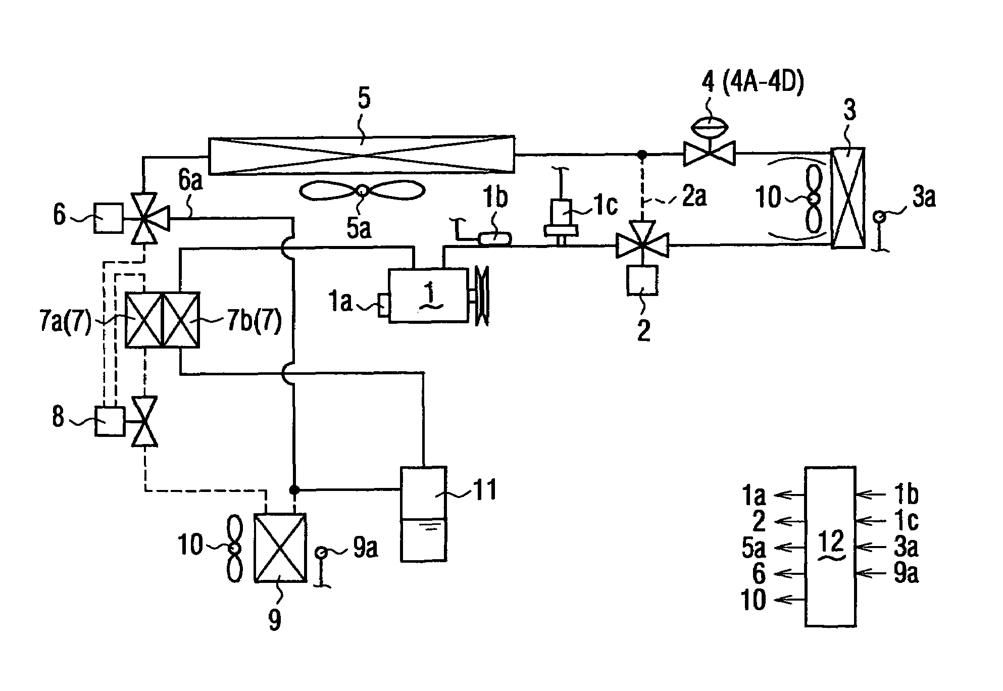
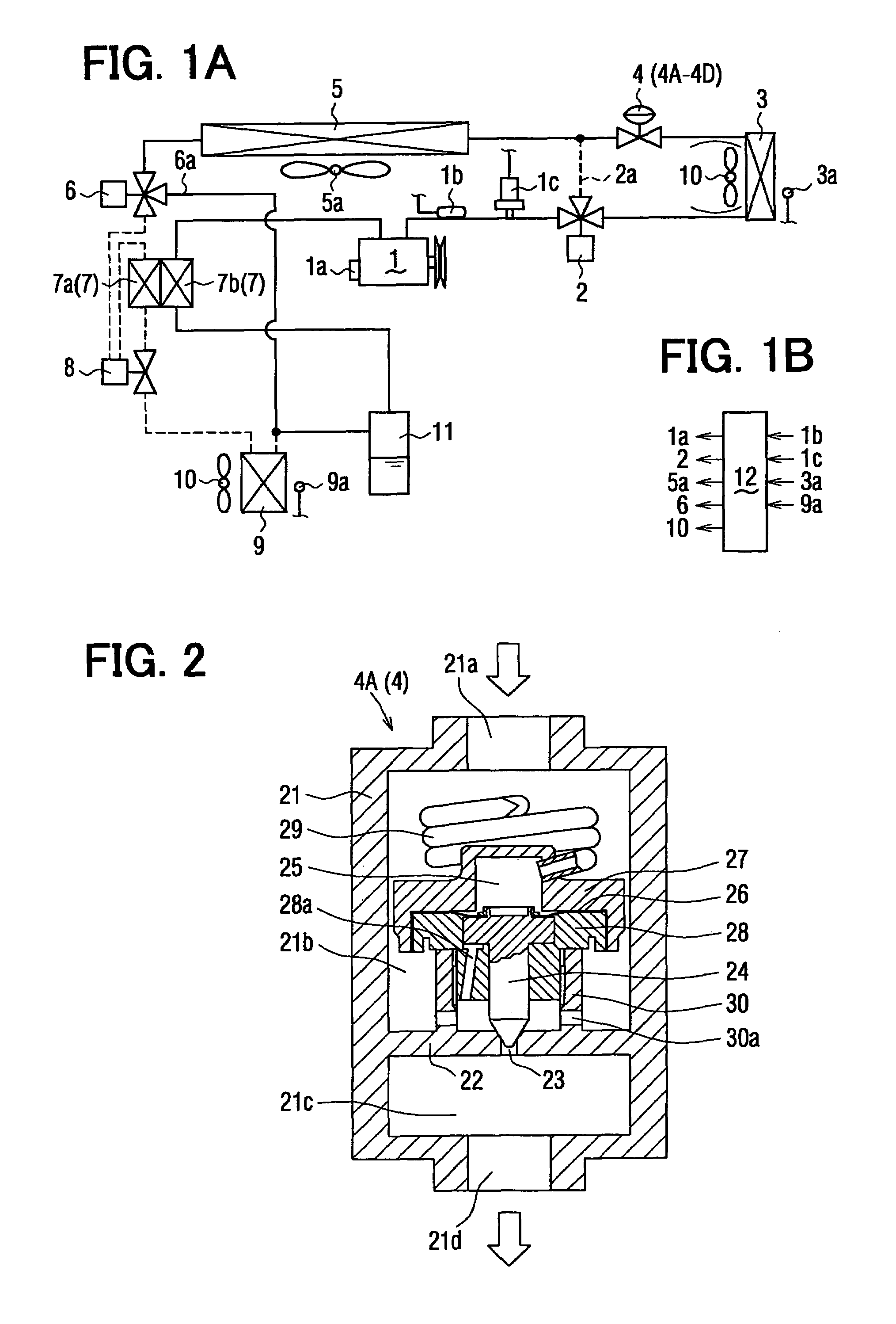
[0028]In the first exemplary embodiment, a mechanical expansion valve 4A is typically used as a pressure control valve 4 for a vapor-compression refrigerant cycle system, for example, a supercritical heat pump cycle system. In a heating operation, refrigerant flows along the solid line shown in FIG. 1A in the vapor-compression refrigerant cycle system when the vapor-compression refrigerant cycle system is used for a vehicle air conditioner. As an example, a supercritical heat pump cycle system is used as the vapor-compression refrigerant cycle system, and CO2 is used as the refrigerant in the supercritical heat pump cycle system.

[0029]A compressor 1 for compressing gas refrigerant is driven by a driving force from a vehicle engine. High-temperature and high-pressure refrigerant discharged from the compressor 1 flows to an interior heat exchanger 3 (i.e., gas cooler, refrigerant radiator) through a first electrical three-way valve 2 in the heating operation. The interior heat exchang...

second exemplary embodiment

[0060]FIG. 5A is a sectional view showing a mechanical expansion valve 4B (pressure control valve 4) at a valve-closing state. In this embodiment, when the outside air temperature is lower than a low value, the valve port 23 is opened by an opening degree, so that refrigerant flows at a start time of the compressor 1 by an amount equal to or larger than a necessary smallest amount.

[0061]In the mechanical expansion valve 4B, the structures having functions similar to those of the mechanical expansion valve 4A are indicated by the same reference numbers. A transmission rod (push rod) 31 is connected to a valve body 32, and the valve body 32 is disposed in the downstream space 21c of the valve port 23 to open and close the valve port 23 from the downstream space 21c by a biasing force of the coil spring (elastic member) 33.

[0062]Furthermore, the transmission rod 31 contacts the valve body 32 at its tip ends. When the temperature around the sealed space 25 is lower than a predetermined ...

third exemplary embodiment

[0069]FIG. 6 shows a valve-closing state of a mechanical expansion valve 4C (4) used in a heating operation according the third exemplary embodiment.

[0070]In the above-described first exemplary embodiment, when the valve port 23 is closed by the valve body 24, refrigerant does not passes through the mechanical expansion valve 4A and refrigerant does not circulate to the interior heat exchanger 3. However, in this embodiment, a bypass hole 22a is provided in the partition wall 22 in a mechanical expansion valve 4C (4), as shown in FIG. 6. In the mechanical expansion valve 4C, the other structure may be formed similarly to that of the mechanical expansion valve 4A.

[0071]In the mechanical expansion valve 4C (4) of this embodiment, a predetermined refrigerant flows through the bypass hole 22a even when the valve port 23 is closed by the valve body 24. Gas is sealed in the sealed space 25 by a density that is in a range between a saturated liquid density at a refrigerant temperature of 0...


PUM


Abstract

A pressure control valve includes a valve portion disposed in a passage from a refrigerant radiator to a suction port of a refrigerant compressor in a vapor-compression refrigerant cycle system. The valve portion controls a refrigerant pressure at an outlet of the refrigerant radiator in accordance with a refrigerant temperature at the outlet of the refrigerant radiator, and the valve portion has a control pressure characteristic in which a pressure change relative to a temperature is smaller than that of the refrigerant. Furthermore, the valve portion may have a fluid passage through which refrigerant flows even when a valve port of the valve portion is closed by a valve body. Accordingly, when the refrigerant radiator is used for heating a fluid, heating capacity for heating the fluid can be rapidly increased at a heating start time.

Description

CROSS REFERENCE TO RELATED APPLICATION[0001]This application is based on Japanese Patent Application No. 2004-171746 filed on Jun. 9, 2004, the contents of which are incorporated herein by reference in its entirety.FIELD OF THE INVENTION[0002]The present invention relates to a pressure control valve for controlling an outlet pressure of a refrigerant radiator (e.g., gas cooler) in a vapor-compression refrigerant cycle system (e.g., supercritical heat pump cycle system). The vapor-compression refrigerant cycle system may be suitably used for a vehicle air conditioner having a heating function for heating a passenger compartment.BACKGROUND OF THE INVENTION[0003]In a supercritical heat pump cycle system using CO2 as refrigerant, for example, a gas cooler is used for heating a fluid, and an externally driven decompression device such as an electrical expansion valve is provided for controlling the operation state of the cycle system. However, in this case, a pressure sensor for detectin...

Claims


Application Information

Patent Timeline
Patent Type & Authority Patents(United States)
IPC IPC(8): F25B41/04F25B1/00B60H1/00F25B7/00F25B9/00F25B40/00F25B41/06F25B49/02
CPCF25B9/008F25B49/02F25B40/00F25B2309/061F25B2700/2102F25B2500/31F25B2600/0271F25B2600/17F25B2600/2501F25B2400/0403
Inventor OHTA, HIROMI
Owner DENSO CORP
Why Eureka
Try Eureka