Fuel-evaporated gas processing system and electromagnetic valve device

a technology of electromagnetic valve and processing system, which is applied in the direction of condensed fuel collection/return, charge feed system, non-fuel substance addition to fuel, etc., can solve the problems of reducing the durability of electromagnetic valve for the increased number of times of operation per unit time, narrowing the control range, and serious problems such as the above mentioned problems, to achieve the effect of efficient suppression of pressure pulsations and efficient reduction of degradation

Active Publication Date: 2009-10-27
MITSUBISHI ELECTRIC CORP
View PDF15 Cites 2 Cited by
  • Summary
  • Abstract
  • Description
  • Claims
  • Application Information

AI Technical Summary

Benefits of technology

[0022]According to the fuel-evaporated gas processing system of the present invention, since the first and the second electromagnetic valves are driven, and the pressure pulsations arising from the opening operation or the closing operation of those electromagnetic valves are mixed within the chamber, it enables efficient suppression of the pressure pulsations and efficient reduction of the degradation of the control of an air fuel ratio or the piping vibrations and the pulse sound of the purge passage caused by those pressure pulsations.
[0023]According to the electromagnetic valve device of the present invention, the first and second electromagnetic valves and the chamber are integrally combined, which enables the efficient conflation of the pressure pulsations resulting from the opening operation or the closing operation of the first and the second electromagnetic valves in the chamber, and permits the easy securement of an installation space therefor in a downsized engine room.

Problems solved by technology

The increased flow rate augments the pressure pulsations in the purge passage, and this has a tendency for the above-mentioned problems to be serious.
However, although the method can reduce the pressure pulsations, the durability of the electromagnetic valve is decreased for the increased number of times of operation per unit time.
Moreover, increasing the control frequency shifts a duty ratio that enables the electromagnetic valve to rise from a closed state to an opened state, to a high ratio, narrowing the control range and lowering the control resolution consequently.
In the meantime, since there are engines of various specifications, the system shown in FIG. 12 does not always match those engines.
Moreover, in the system shown in FIG. 12, it lacks compactness of the components with the increase of their number as the electromagnetic valve A or the electromagnetic valve B are separately provided in the respective branched purge passages and individually control those electromagnetic valves.
Furthermore, in the technique shown in FIG. 12, while two electromagnetic valves are used and controlled with a phase difference of ½ cycles in order to double an apparent control frequency, a pressure response delay has not been considered at all from the time when an opening or a closing operation of the electromagnetic valve is executed to the time when the operation is reflected upon the response as a pressure fluctuation of the purge passage.

Method used


Image

  • Fuel-evaporated gas processing system and electromagnetic valve device
  • Fuel-evaporated gas processing system and electromagnetic valve device
  • Fuel-evaporated gas processing system and electromagnetic valve device

Examples


first embodiment

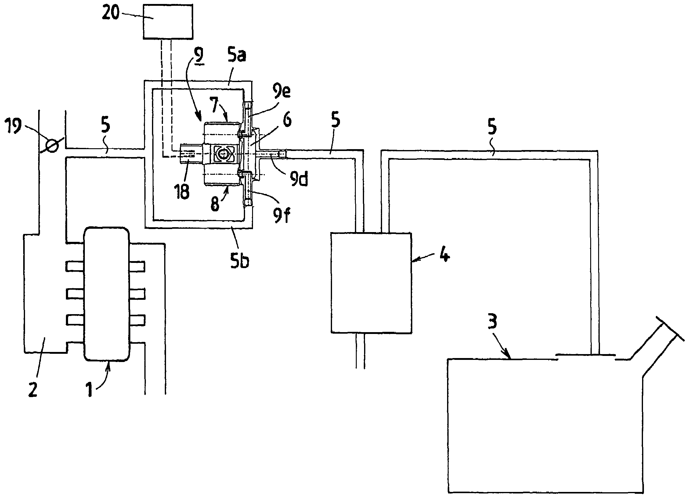
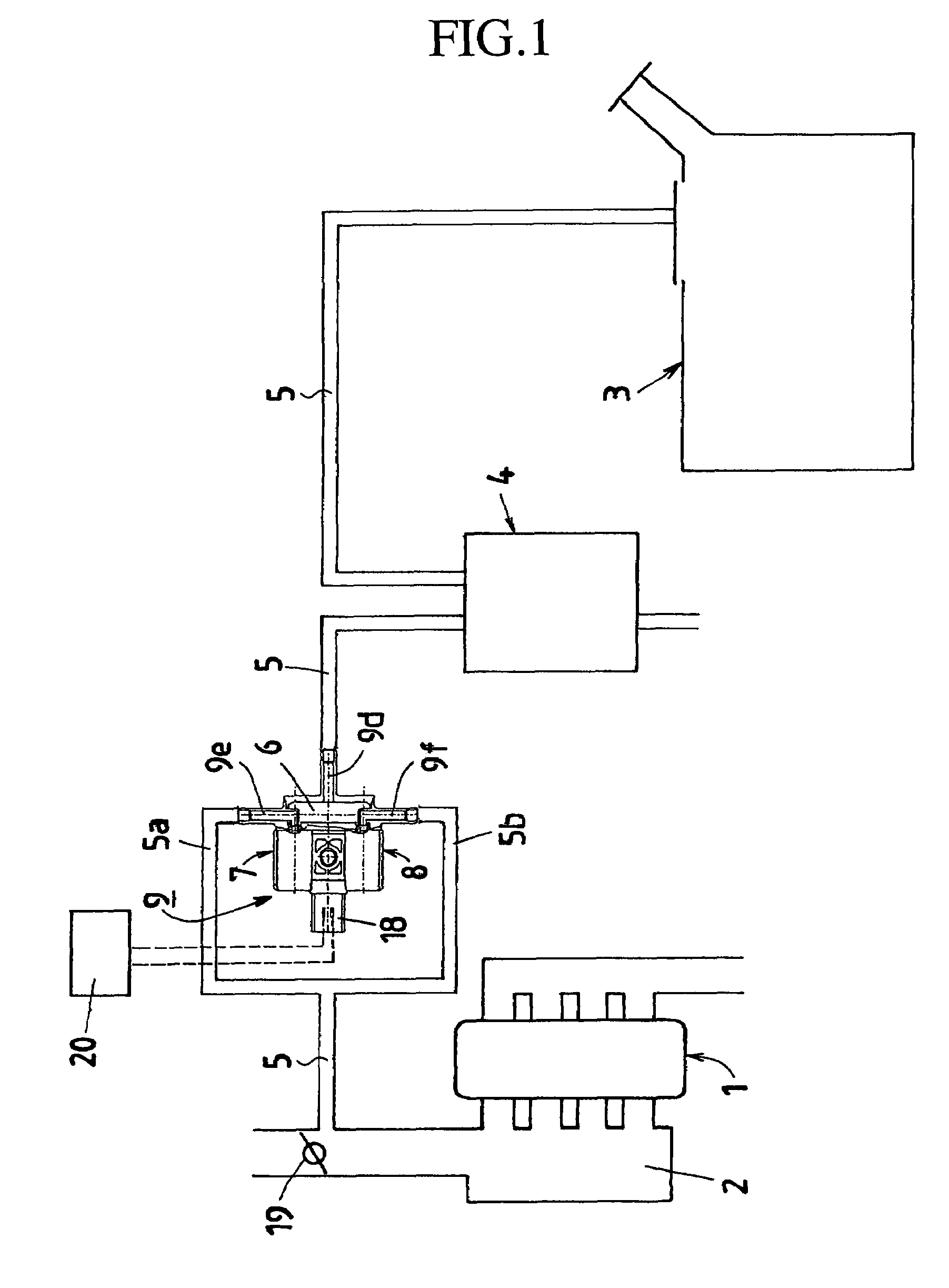
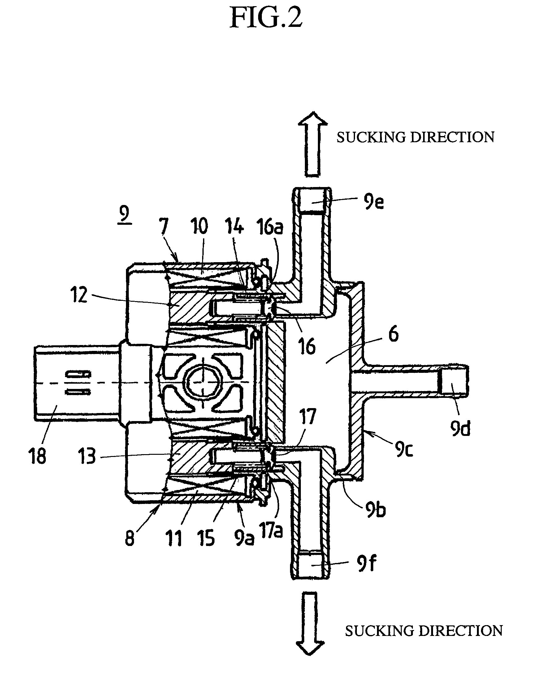
[0037]FIG. 1 is a schematic view showing a fuel-evaporated gas processing system according to the first embodiment of the present invention, FIG. 2 is an enlarged sectional view showing a valve unit as the electromagnetic valve device shown in FIG. 1, and FIG. 3 is an enlarged sectional view showing the important points of one of electromagnetic valve systems of the valve unit illustrated in FIG. 2.

[0038]As shown in FIG. 1, a purge passage 5 for taking in and processing evaporated gas evaporated within a fuel tank 3 is connected to an intake pipe constituting part of an intake system of an engine 1. A position at which the purge passage is connected to the intake pipe is located in a portion which is situated at downstream from a throttle valve 19 described later and at which negative pressure can be produced. A surge tank 2 is provided at a position located more downstream therefrom. The purge passage 5 is composed of a series of passages such as a passage introducing the evaporate...

second embodiment

[0065]In the first embodiment, the example is given where the electromagnetic valve 7 and the electromagnetic valve 8 having almost the same flow rate characteristic are used. However, combining the electromagnetic valves having a different characteristic enables achieving the required flow rate characteristic. In the second embodiment, an example will be explained where electromagnetic valves having a different flow rate characteristic are used.

[0066]FIG. 8 shows a flow rate characteristic of the electromagnetic valve of the forward suction type where negative pressure acts in a valve closing direction, represented in coordinates in which the duty ratio is taken as a horizontal axis and the flow rate is taken as a vertical direction with respect to each duty ratio. The electromagnetic valves 7, 8 used in the first embodiment are electromagnetic valves of the forward suction type having a flow rate characteristic like that shown in FIG. 8. FIG. 9 shows a flow rate characteristic of ...

third embodiment

[0077]In the second embodiment, the ingenuity is racked that in the low flow rate area where jumping may occur, only the electromagnetic valve 8 of the reverse suction type is driven, and in the flow rate area where the rate is larger than that in the low flow rate area, in which jumping hardly occurs, both the electromagnetic valve 7 of the forward suction type and the electromagnetic valve 8 of the reverse suction type are driven. In the second embodiment, the same maximum flow rate is used in the electromagnetic valve 7 and the electromagnetic valve 8.

[0078]In contrast thereto, in the third embodiment, the electromagnetic valve 8 of the reverse suction type has the maximum flow rate smaller than that of the electromagnetic valve 7 of the forward suction type.

[0079]For example, when the flow rate accomplished when both the electromagnetic valve 7 and the electromagnetic valve 8 are driven at a duty ratio of 100% is assumed to be the maximum flow rate of the purge passage, the elec...


PUM


Abstract

A fuel-evaporated gas processing system includes an input port taking in evaporated gas evaporated in a fuel tank; output ports supplying the evaporated gas taken in through the input port to an intake system of an engine; a chamber interposed between the input port and the output ports; an electromagnetic valve device including at least first and second electromagnetic valves disposed in the connection between the input port or the output ports and the chamber, either of the input port or the output ports being branched off into a plurality of sections, and perform opening and closing operations in response to a driving signal; and a valve control means driving the first and the second electromagnetic valves of the electromagnetic valve device.

Description

TECHNICAL FIELD[0001]The present invention relates to a fuel-evaporated gas processing system and an electromagnetic valve device controlling the flow rate of evaporated gas from a fuel tank to be fed to an intake system of a motor engine.BACKGROUND ART[0002]In general, an intake system of a motor engine is arranged to be fed with evaporated gas evaporated within a fuel tank. A feeding path therefor is called as a purge passage, and consists of the fuel tank; a canister taking in the evaporated gas evaporated in a fuel tank and temporarily adsorbing the gas therein; and a series of piping connecting the main elements such as the intake system of the engine etc, receiving the evaporated gas (purge gas) discharged from the canister. Further, an electromagnetic valve used for duty control of the flow rate of the purge gas is provided between the canister of the purge passage and the intake system of the engine.[0003]Here, suppose that the intake system of the engine and the canister ar...

Claims


Application Information

Patent Timeline
Patent Type & Authority Patents(United States)
IPC IPC(8): F02M33/02
CPCF02M25/0827F02M25/089F02M25/0836
Inventor UEDA, MASATOSHIMATSUMOTO, TATSUYA
Owner MITSUBISHI ELECTRIC CORP
Why Eureka
Try Eureka