
Shoaling water energy conversion device

a technology of energy conversion device and water float, which is applied in water-power plants, machines/engines, electric generator control, etc., can solve the problems of reducing affecting the production of energy, and affecting the efficiency of the device, so as to achieve greater efficiency, enhance the production of energy, and increase the effect of electrical energy

Inactive Publication Date: 2009-10-27
THORSBAKKEN ARDEN L
View PDF77 Cites 11 Cited by
  • Summary
  • Abstract
  • Description
  • Claims
  • Application Information

AI Technical Summary

Benefits of technology

[0016]The present invention includes a shoaling water energy conversion device capable of producing electrical or mechanical energy from the motion of waves or moving water. A device having features of the present invention includes a body or collection chamber that surrounds a hydro-turbine that is activated by the flow of water through the device as a wave front passes by or as water flows into the device. The water is confined and directed into the hydro-turbine by the body, which may include lateral wings that face the incoming waves and / or a wave leveler (a catch plate, blade or attachment that flattens incoming waves and directs the flow of the waves into the unit), thereby increasing both the volume and velocity of the flow through the device.
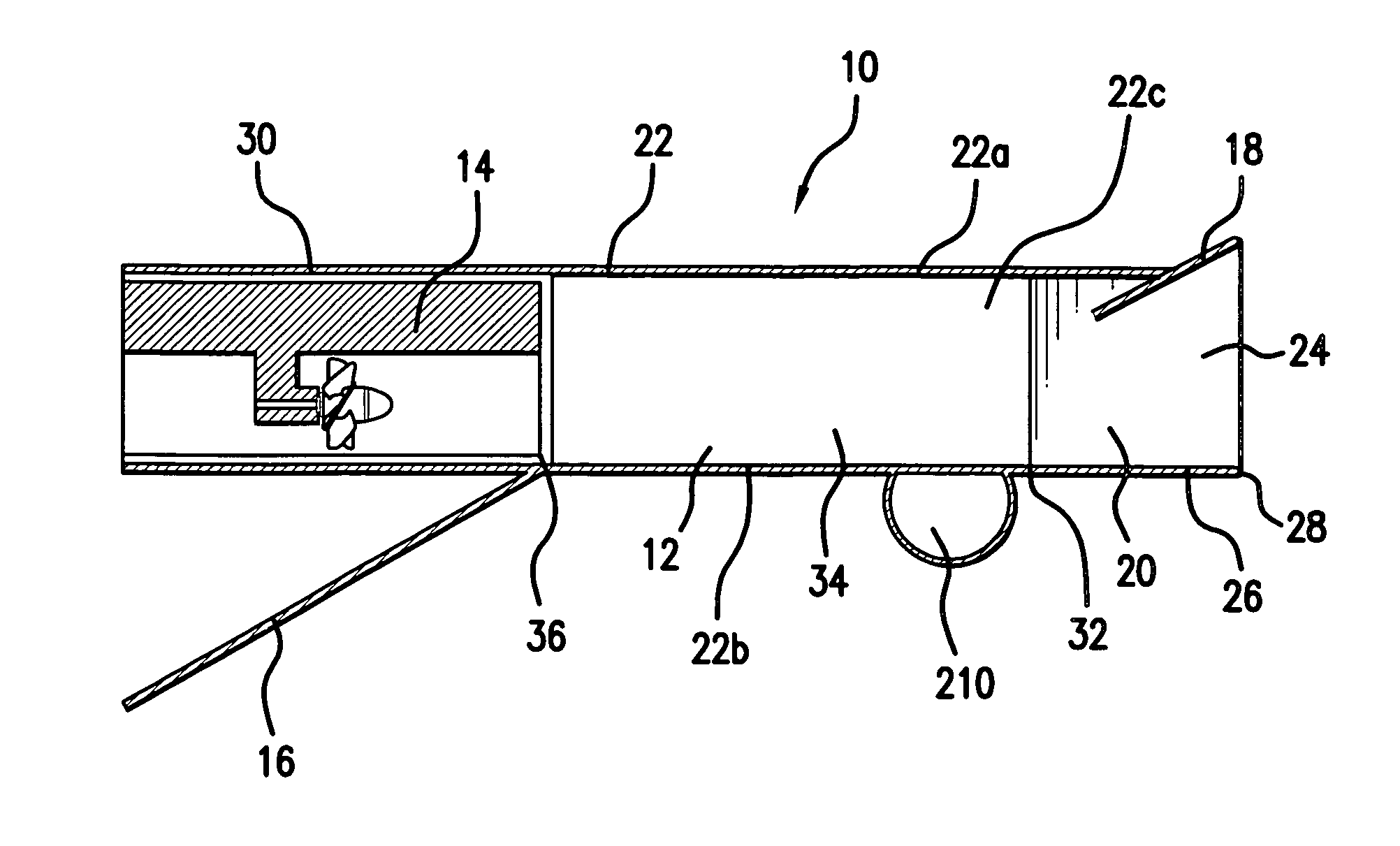
[0017]The present invention preferably includes an apparatus with a water foil or clear out channel flange which keeps the exit or exhaust of the device free of water, such that water that has flowed through the device may exit freely from the device without interference from back pressure produced by exterior water that flowed under the device. The use of this water foil or clear out channel flange allows the device to be used directly within the wave front. The “water foil” or “splash out” plate that keeps the exit from the body clear of water is located on the underside of the device, at or near the posterior end of the body. The water foil or splash out plate enhances the efficiency of the device by giving the water flowing through the device free exit therefrom into a void area in the surrounding water, without interference from the back pressure caused by water adjacent to the exit. Alternatively, the water foil or clear out channel flange may be omitted and the water flowing through the device may exit into a smaller void area created by the body of the device itself. While the void area created by the device itself absent the water foil or clear out channel may be smaller than that created by utilizing the clear out channel flange, in some circumstances it may be sufficient to allow free exit from the device without interference from the back pressure caused by water adjacent to the exit.
[0018]The front edge of the body or collection chamber faces the incoming waves and is designed to penetrate an incoming wave above the trough of the wave, such that a significant portion of the wave breaks and overtops the lower edge of the body and rushes through the device. The body or collection chamber directs the water through the hydro-turbine as it flows through the device, thereby producing energy.

Problems solved by technology

Since wave energy and energy from flowing water are renewable resources, the environmental impact is limited to the resources used for the production, installation, and dismantling of the device itself.
The floats of these devices also often have size limitations that are dependent upon the size of the waves, since the “rolling” of the float in the wave or the riding of the float over the troughs of the waves (i.e. stretching between two wave crests) reduces the efficiency of the device.
The length of the pipe is subject to size limitations, as the efficiency of the device drops if the pipe is too large relative to the size of the waves.
The limitations on the energy extraction of these devices are largely dependent upon the necessity of matching the design of the device to the type and size of the waves that will be encountered.
As such, these devices are less effective in areas where the wavelength and size of waves is variable.
Most of the energy lost during the operation of roller type devices is due to friction between the water and the surface of the device.
These devices may extract both kinetic and potential energy from the waves, but energy is often lost due to the uneven pulsating character of the energy delivery, regardless of whether a firm or flexible body is used.
The limitations of these devices often depend upon the particular design.
Both “wash up” and “flush in” devices will lose energy due to friction as the waves shoal up into and over the device.
In general, wave energy conversion systems that are located offshore in deep water have the advantage of having larger waves from which to produce energy, with the disadvantage of requiring longer and more expensive underwater cables to transmit the energy to shore and more difficultly in performing maintenance on the system.
On the other hand, onshore or near-shore units have the advantage of easier maintenance and installation, a shorter length of underwater cable needed to transmit the energy to shore, and not requiring deep-water moorings, but have the disadvantages of having smaller waves from which to product energy and, in some cases, meeting resistance from nearby residents due to its aesthetic effects on the shoreline.
While conventional wave energy conversion systems have been successfully developed and utilized, they are not without problems.
In particular, conventional wave energy conversion systems often operate at a lower efficiency than may be desirable due to the energy loss from the wave caused by the wave's interaction with the device itself (for example, the loss of energy through the shoaling of the wave on the device and the back-pressure effect which occurs when the water is unable to properly be “cleared-out” from the exit of the device).
Likewise, conventional shoaling water energy conversion devices have been limited to one method or type of energy conversion, thereby reducing the amount of energy produced by the systems.

Method used


Image

  • Shoaling water energy conversion device
  • Shoaling water energy conversion device
  • Shoaling water energy conversion device

Examples


Embodiment Construction

)

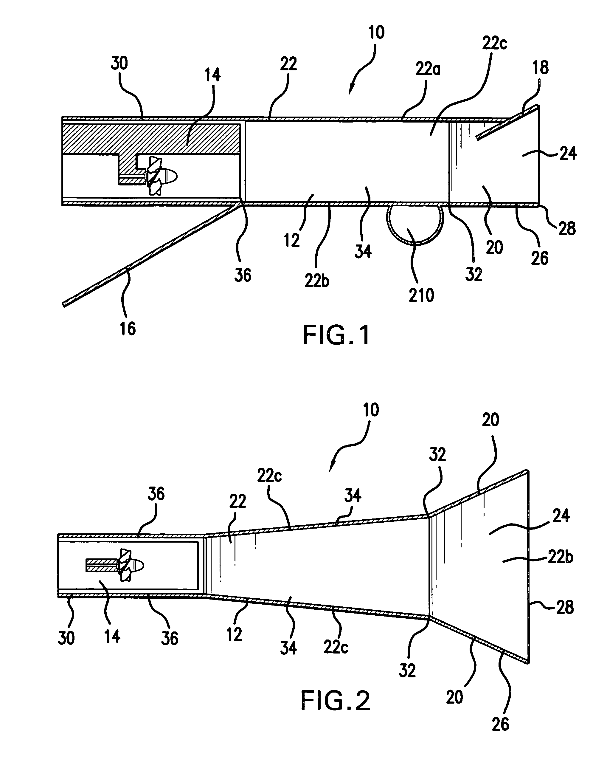
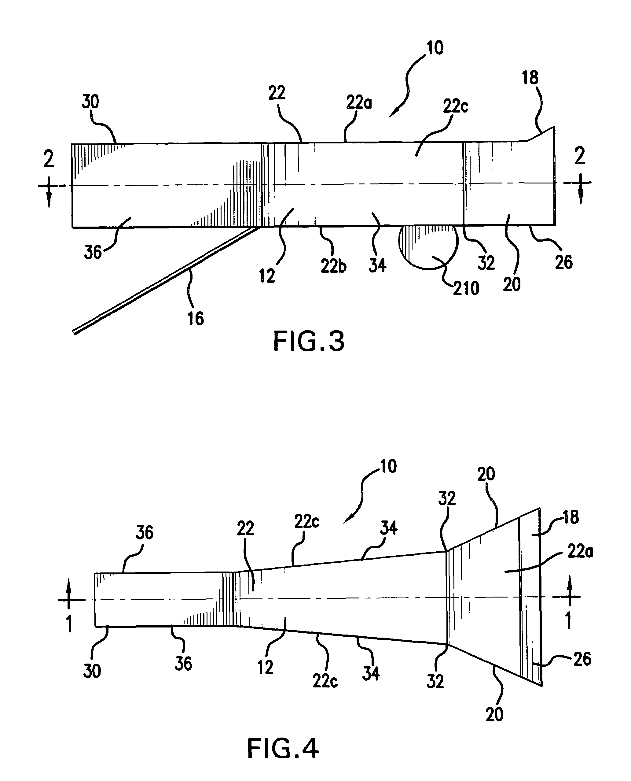
[0035]Referring to FIGS. 1-6, a shoaling water energy conversion device 10 having features of the present invention is shown. The shoaling water energy conversion device 10 includes a body or collection chamber 12, a hydro-turbine 14, and, preferably, a water foil or clear out channel flange 16. The shoaling water energy conversion device 10 also preferably includes a wave leveler or catch plate 18 and anterior lateral wave confinement blades 20.

[0036]The body 12 preferably includes walls 22 that surround a central channel 24. The walls 22 include a top wall 22a, a bottom wall 22b and two side walls 22c. Alternatively, the body 12 may only three walls, generally in the form of a bottom wall and two side walls. The body 12 has an anterior end 26 and a posterior end 30.

[0037]The body 12 has buoyancy that is sufficient to keep the shoaling water energy conversion device 10 from fully submerging in the water and to allow the shoaling water energy conversion device 10 to rotate relative...


PUM


Abstract

A device for converting the energy of water waves or flowing water into electrical or mechanical energy. The device includes a body or collection chamber with a hydro-turbine located opposite the water entrance and, preferably, a water clear out channel flange located beneath the hydro-turbine and at or upstream of the water exhaust from the device. As the water is channeled by wave facing directional blades and a wave leveler through and exits the hydro-turbine or pump, it has free exit into a water void area which is produced by the deep water, with its own flotation apparatus or moorings, or near shore, held by supports secured to the seabed or other structures. The device also exhibits a “tip up, tip down” synchronous motion as wave fronts advance through and passed the device, which increases the efficiency of the device by accelerating the flow of water therethrough.

Description

CROSS-REFERENCE TO RELATED APPLICATION[0001]This application is based upon and claims the benefit of U.S. Provisional Application Ser. No. 60 / 713,783, filed Aug. 29, 2005, and U.S. Provisional Application Ser. No. 60 / 725,255, filed Oct. 11, 2005.BACKGROUND OF THE INVENTION[0002]The present invention is directed to a shoaling water energy conversion device and, more particularly, to a shoaling water energy conversion device for use in oceans, lakes, rivers, and other bodies of water.[0003]The general idea of harnessing the power of waves in an ocean or a lake, or the current of a river, to produce energy has been around for many centuries. Water wheels were used to irrigate farmland and to process the crops grown thereon since antiquity. The various devices developed met with differing levels of success, but, until recently, the devices were generally used as a direct source of power. That is, the devices usually converted the power of the waves or current directly into mechanical en...

Claims


Application Information

Patent Timeline
Patent Type & Authority Patents(United States)
IPC IPC(8): F03B13/18
CPCE02B9/08F03B13/22F03B17/061Y02E10/38F05B2240/97Y02E10/28F05B2240/932Y02E10/30Y02E10/20
Inventor THORSBAKKEN, ARDEN L.
Owner THORSBAKKEN ARDEN L
Learn More