

Spring loaded tool with floating depth control for countersinking holes or engraving
a technology of depth control and countersinking holes, which is applied in the field of tool holders, can solve the problems of inability to meet the needs of specific processes, engraving and countersinking holes, and the surface of workpieces are susceptible to variations, so as to prevent scratching of delicate workpieces, prevent damage to workpieces, and improve the effect of devices
- Summary
- Abstract
- Description
- Claims
- Application Information
AI Technical Summary
Benefits of technology
Problems solved by technology
Method used
Image

Examples
Embodiment Construction
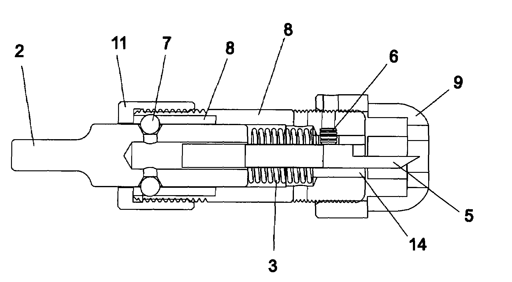
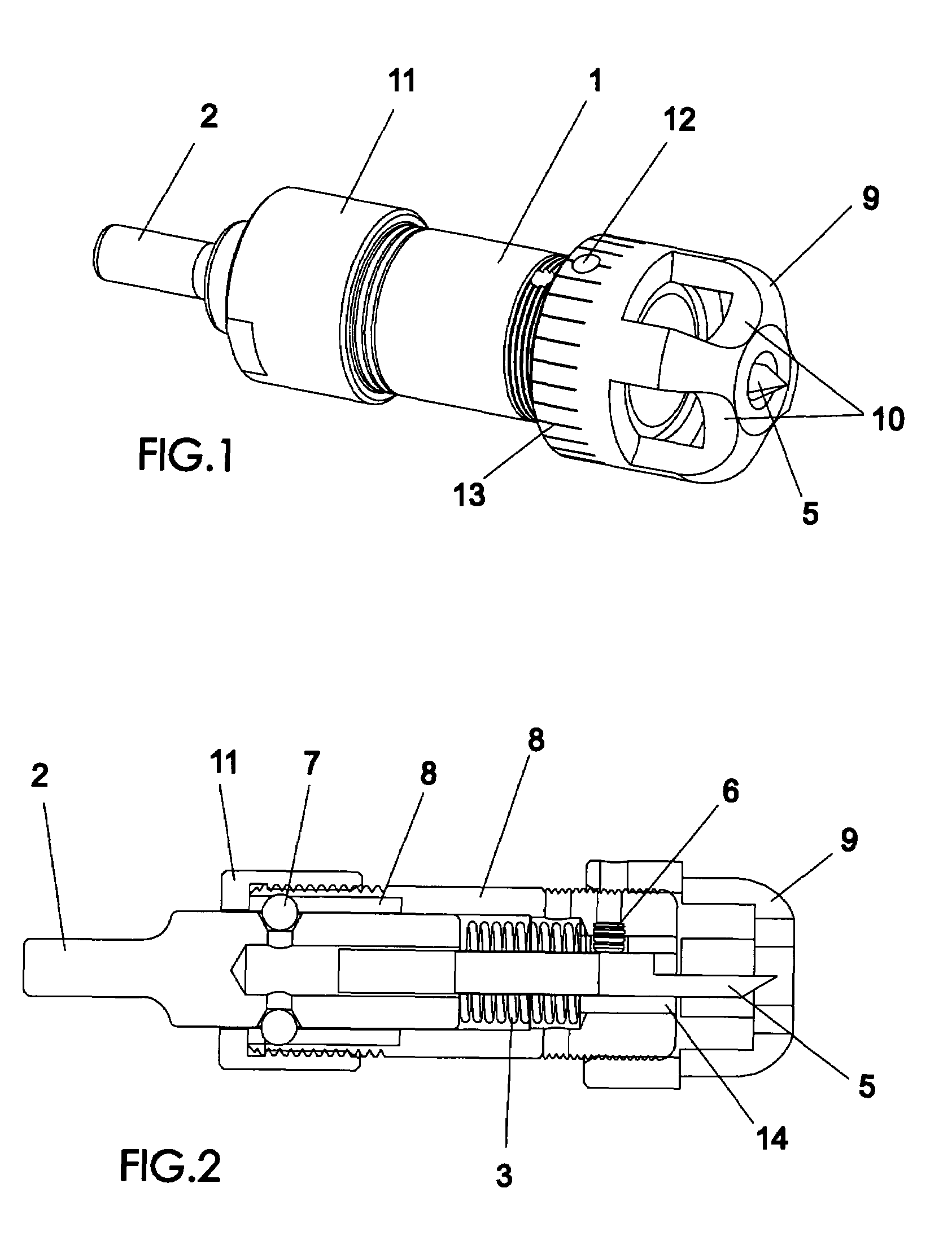
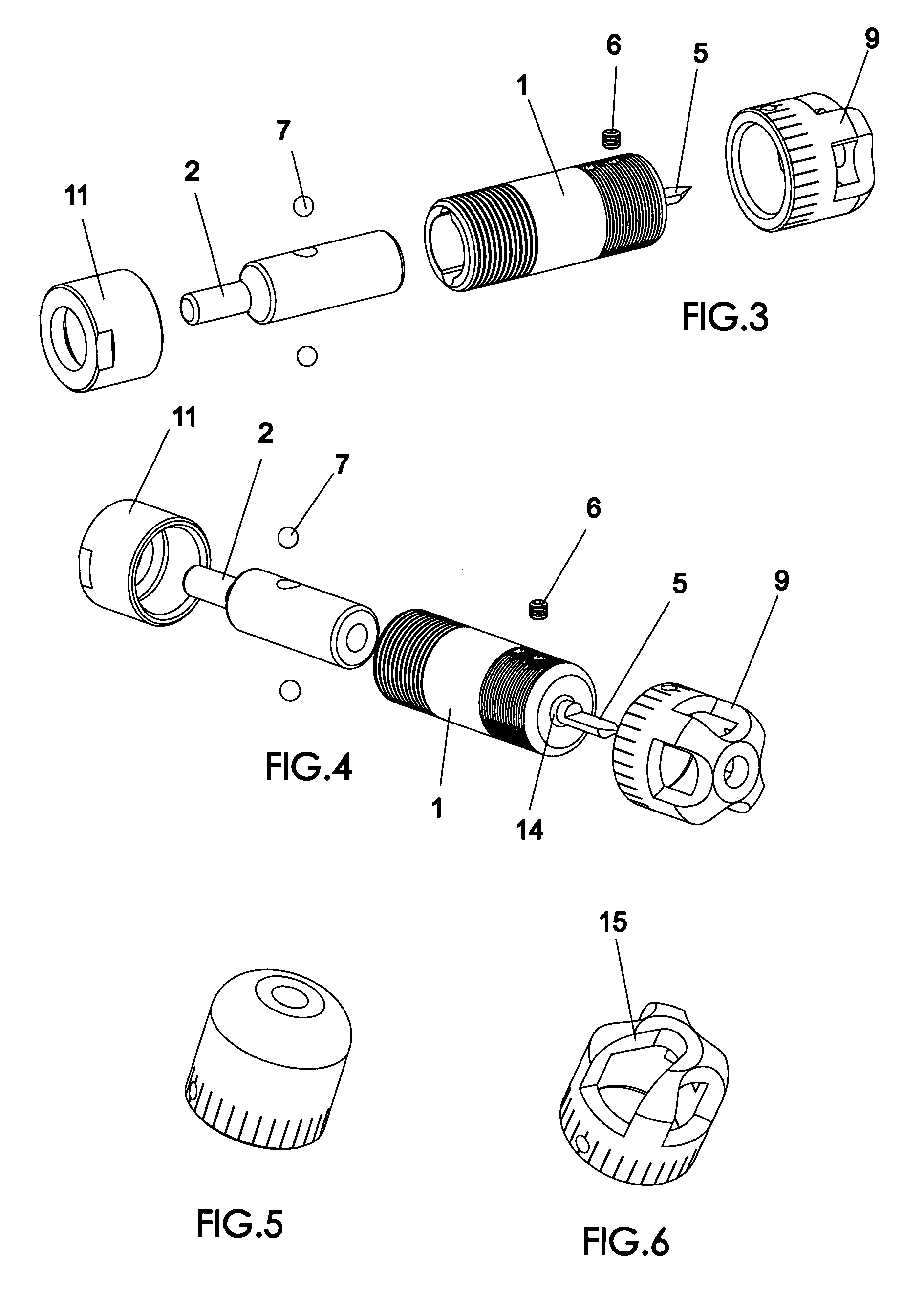
[0007]The objectives set forth above are met in accordance with the present invention, whereby a depth controlling nosepiece is attached to a spring loaded toolholder to allow engraving or countersinking holes to a defined depth. Although the devices of my aforesaid patents work well for engraving and would also work for countersinking holes, several modifications are provided in accordance with the present invention which significantly improves the devices. First, the nosepiece is modified so it has large cutout areas surrounding the tool-bit. This provides room for the larger chips that are created when countersinking holes to be expelled from the internal area of the nosepiece to prevent damage to the work-piece. Additionally, a bearing may be placed on the end of the nosepiece so that when the nosepiece is pressed against the work-piece, the bearing rotates so that the nosepiece portion pressed against the work-piece does not continue spinning. This prevents scratching of delica...
PUM
| Property | Measurement | Unit |
|---|---|---|
| depth | aaaaa | aaaaa |
| protrusion distance | aaaaa | aaaaa |
| distance | aaaaa | aaaaa |
Abstract
Description
Claims
Application Information