
Turbine component with tip flagged pedestal cooling

a turbine and pedestal cooling technology, applied in the direction of liquid fuel engines, machines/engines, mechanical equipment, etc., can solve the problems of ineffective cooling, insufficient cooling, and insufficient cooling of the radially outermost portion of the airfoil at the trailing edg

Active Publication Date: 2009-10-27
RTX CORP
View PDF13 Cites 25 Cited by
  • Summary
  • Abstract
  • Description
  • Claims
  • Application Information

AI Technical Summary

Benefits of technology

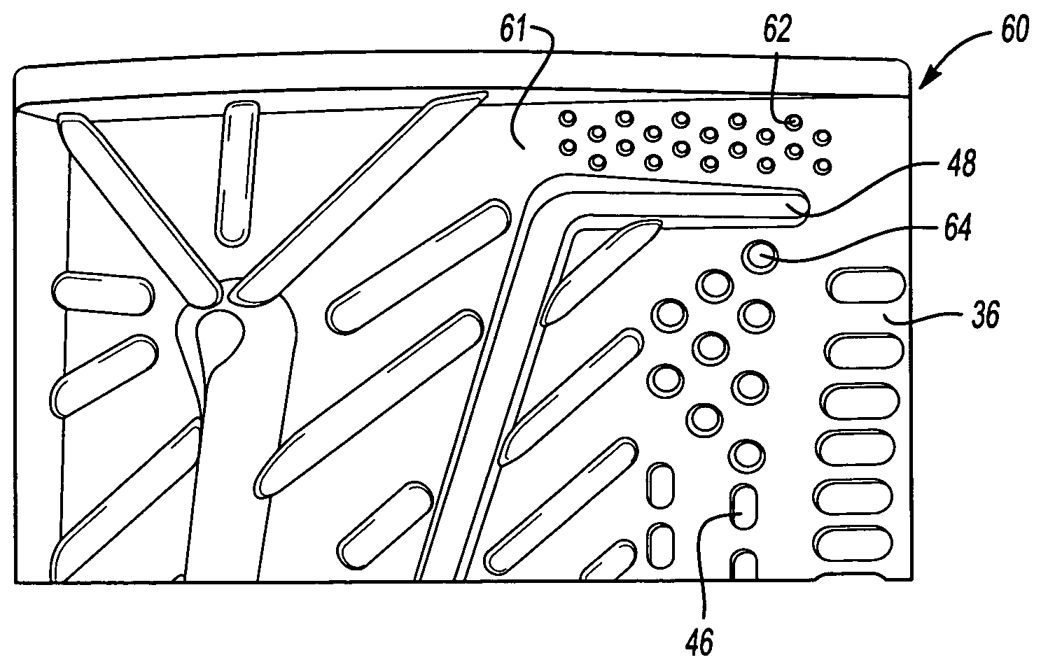
"The invention provides additional cooling at the outer edge of a turbine component with an airfoil by using a tip flag with a heat transfer pedestal array. This helps to remove additional heat from the airfoil and improve the cooling of the radially outermost portions of the airfoil. The last few metering holes are replaced by a pedestal array to provide additional heat transfer surfaces. This feature helps to improve the efficiency and performance of the turbine component."

Problems solved by technology

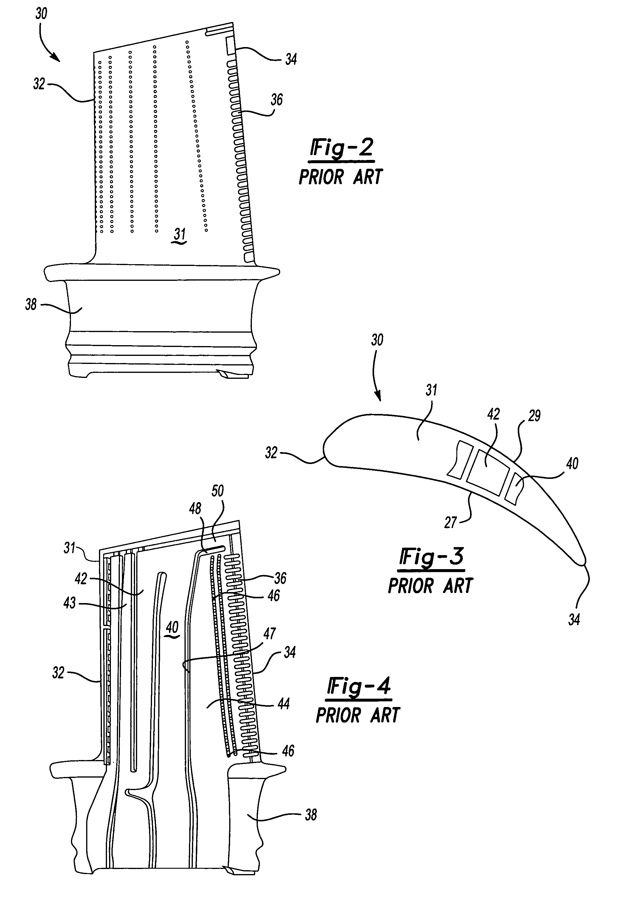
In the prior art the cooling of the radially outermost portion of the airfoil at the trailing edge has proven problematic.
As such, cooling is not as effective as it is at radially inner locations.
However, additional cooling is still necessary.
These tip strips create turbulence in the airflow, and thus increase cooling.
Even so, there are still problems with spallation of external coatings, burning, and oxidation at the area in question.

Method used


Image

  • Turbine component with tip flagged pedestal cooling
  • Turbine component with tip flagged pedestal cooling
  • Turbine component with tip flagged pedestal cooling

Examples


Embodiment Construction

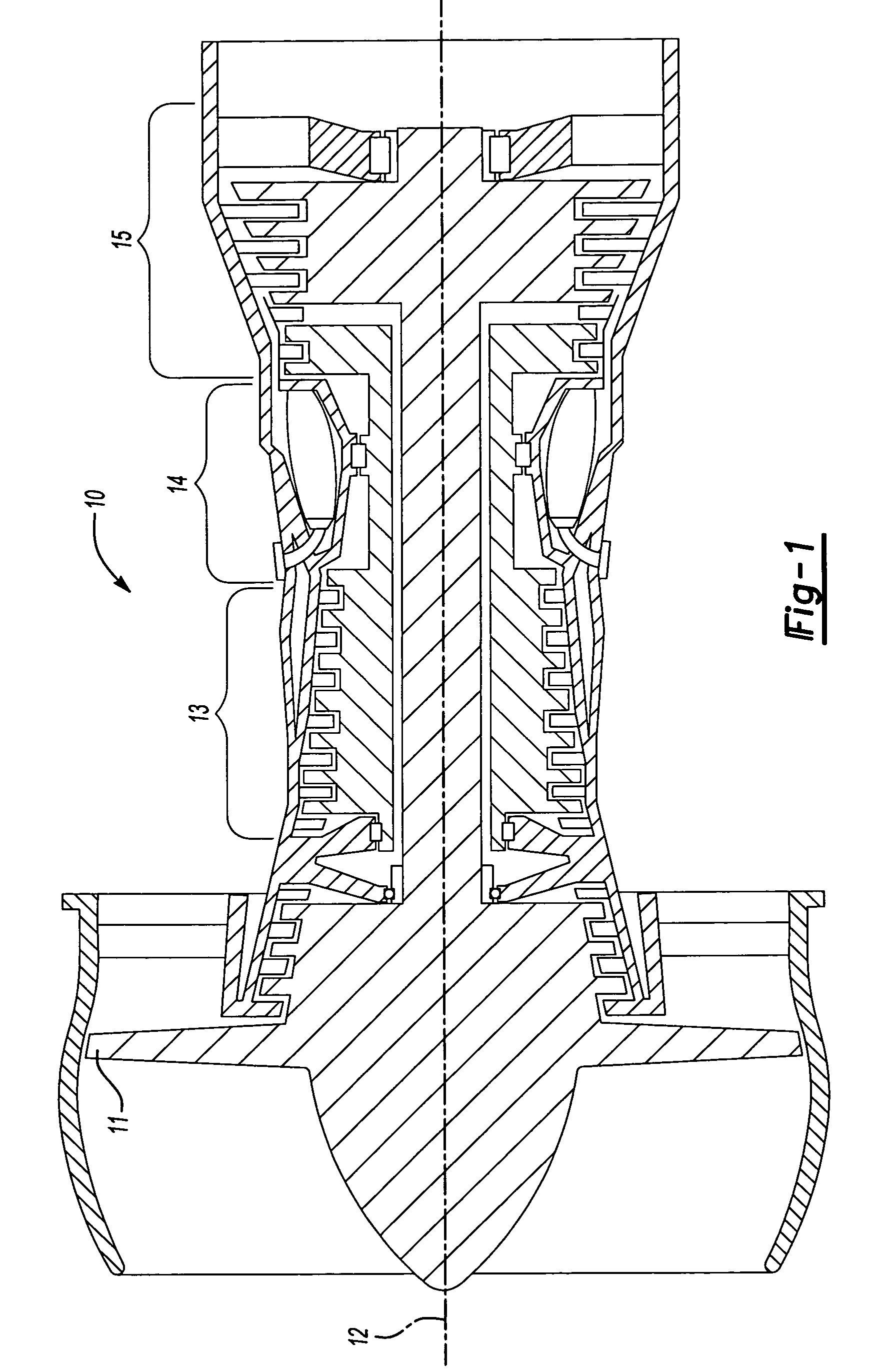
[0015]FIG. 1 shows a gas turbine engine 10, such as a gas turbine used for propulsion, circumferentially disposed about an engine centerline, or axial centerline axis 12. The engine 10 includes a fan 11, a compressor section 13, a combustion section 14 and a turbine section 15. As is well known in the art, air compressed in the compressor section is mixed with fuel which is burned in the combustion section 40 and expanded in turbine section 15. The air compressed in the compressor section and the fuel mixture expanded in the turbine section 15 can both be referred to as a hot gas stream flow. The turbine section 15 includes rotors that, in response to the expansion, rotate, driving the compressors and fan. The turbine 15 comprises alternating rows of rotary blades 30 and static airfoils or vanes 19. FIG. 1 is a somewhat schematic representation, for illustrative purposes only, and is not a limitation of the instant invention, that may be employed on gas turbines used for power gener...


PUM


Abstract

A turbine blade for a gas turbine engine is provided with improved cooling at a radially outer portion of the trailing edge. A tip flag path is provided with a first pedestal array to increase the heat transfer at the area. In addition, a second pedestal array replaces the metering holes which has been positioned radially inwardly of the tip strip. The two pedestal arrays provide improved heat transfer at an area which has been subject to burning and spallation in the prior art.

Description

BACKGROUND OF THE INVENTION[0001]This application relates to a cooled turbine component, such as a turbine blade.[0002]Gas turbine engines are known, and include a plurality of sections mounted along a serial flow path. A fan directs air into a compressor where it is compressed. The compressed air is delivered into a combustion section. In the combustion section the compressed air is mixed with fuel and combusted. Products of combustion pass downstream over turbine rotors. The turbine rotors are driven by the products of combustion, and drive the fan and compressor sections. Typically, the turbine includes a plurality of rotors each having circumferentially spaced blades that are removable from the rotor. In addition, stationary vanes are positioned adjacent to the turbine rotors.[0003]The products of combustion are hot, and thus the rotor blades and vanes are exposed to high temperatures. One method to address the high temperatures experienced by the blades is the use of internal a...

Claims


Application Information

Patent Timeline
Patent Type & Authority Patents(United States)
IPC IPC(8): F01D5/08F01D5/18
CPCF01D5/187F05D2240/122F05D2240/304F05D2260/2214F05D2260/221F05D2260/2212F05D2260/22141Y02T50/676Y02T50/60F01D5/08F01D25/08F01D25/12F02C7/12
Inventor CHEROLIS, ANTHONY P.CHRISTOPHEL, JESSE R.ABDEL-MESSEH, WILLIAM
Owner RTX CORP
Learn More