Electrical power system control communications network

a technology of power system control and communication network, applied in the direction of signalling system details, signalling systems, instruments, etc., can solve the problems of inability of power utility firms to reduce power outages and interruptions, difficult to effectively troubleshoot the power system, and insufficient data collection

Active Publication Date: 2009-10-27
EATON INTELLIGENT POWER LTD
View PDF65 Cites 76 Cited by
  • Summary
  • Abstract
  • Description
  • Claims
  • Application Information

AI Technical Summary

Benefits of technology

[0019]Highly flexible and highly reliable control communication networks are disclosed herein that are readily adaptable to existing power system networks at reduced cost relative to existing communication methods. Communication networks of the invention are also universally applicable for different types of devices and equipment and in different and may be used in considerably varying locations, sites, and operating conditions in a power system. Communication networks of the invention are also accommodating of future expansion and modification of the power system. Data may be collected more or less in real time across an entire network at a reasonable cost.

Problems solved by technology

Medium and high voltage electrical generation and transmission systems present complex issues from an oversight, maintenance and control perspective.
Thus far, the capability of power utility firms to reduce power outages and interruptions and to prevent damage associated with electrical faults has been limited by difficulties in collecting sufficient data needed to assess, in a centralized location, operating conditions of the power system at points of interest.
Prudent control decisions, identification of problems areas and concerns, and effective troubleshooting of the power system is difficult without adequate data collection and communication to control centers.

Method used


Image

  • Electrical power system control communications network
  • Electrical power system control communications network
  • Electrical power system control communications network

Examples


Embodiment Construction

[0007]For a full appreciation of the inventive aspects of exemplary embodiments of the invention described below, the disclosure herein will be segmented into different parts. Electrical power systems and associated problems in the art are first discussed in Part I. Conventional data communication methods used for controlling power systems are disclosed in Part II. Exemplary embodiments of the invention are disclosed in Part III.

I. Introduction to Electrical Power Systems

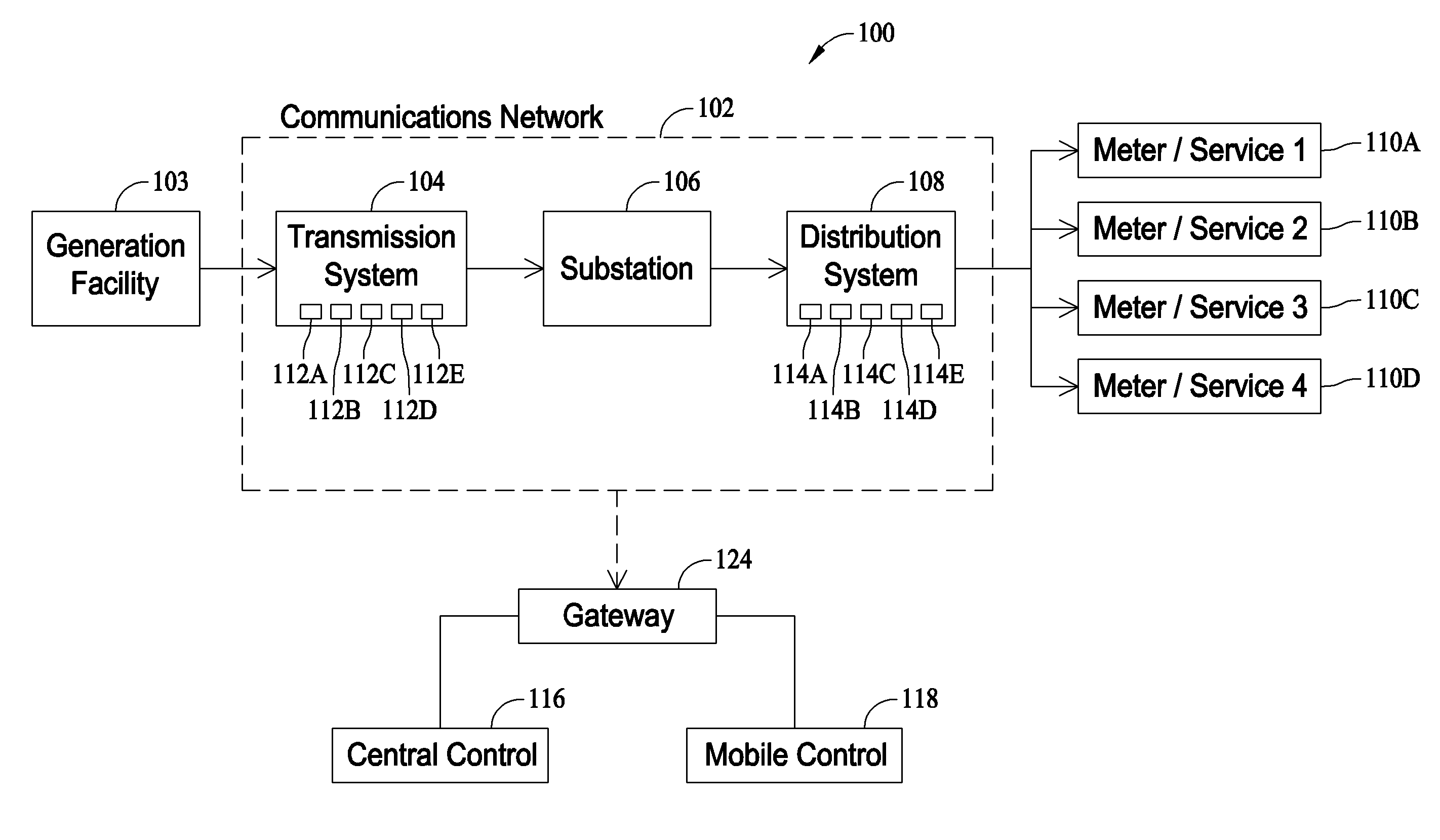
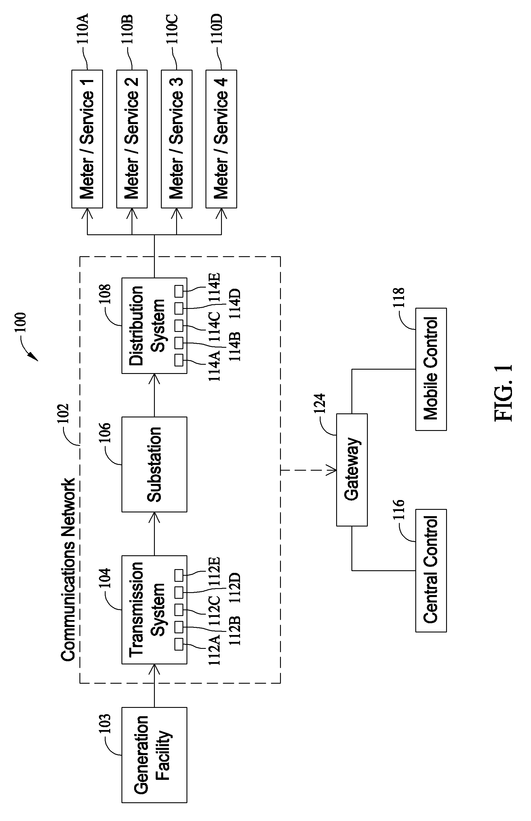
[0008]Electrical power systems operated by electrical utility firms and the like typically include a large number of transformers, capacitor banks, reactors, motors, generators and other major pieces of electrical equipment often interconnected with heavy duty cabling and switching devices for connecting and disconnecting the equipment to the network. The switching devices may be operated manually at the location of the switching devices, automatically in response to command instructions, or remotely from a control ...


PUM


Abstract

Communication networks having redundant signal paths for sensed operating conditions and control parameters for electrical power transmission and distribution systems.

Description

BACKGROUND OF THE INVENTION[0001]This invention relates generally to electrical power systems, and more specifically to systems and methods for monitoring, managing and controlling power transmission and distribution systems.[0002]Medium and high voltage electrical generation and transmission systems present complex issues from an oversight, maintenance and control perspective. The scope of such electrical networks and systems, both in terms of the number of interconnected equipment and devices and the geographic areas covered by the transmission and distribution systems, can be enormous. Efficient operation and control of such electrical networks is key to minimizing power interruptions and outages to scores of residential and commercial customers, and / or containing avoiding fault conditions and associated damage to the power system and / or residential and commercial equipment and devices connected to the power system.[0003]Thus far, the capability of power utility firms to reduce p...

Claims


Application Information

Patent Timeline
Patent Type & Authority Patents(United States)
IPC IPC(8): G08B1/08
CPCH02J13/0075H02J13/0079Y02E60/7853Y04S40/126H02J13/00017H02J13/00026H02J13/00028H02J13/00034Y04S40/124Y02E60/00
Inventor BANTING, JOHN FREDRICKMUENCH, FRANK JOHN
Owner EATON INTELLIGENT POWER LTD
Why Eureka
Try Eureka