Apparatus and method for radar imaging by measuring spatial frequency components

a technology of spatial frequency components and radar imaging, applied in the direction of instruments, measurement devices, and antennas, can solve the problems of adding weight and complexity to the system of antenna gimbals, and the scanning process itself adding aberrations, so as to improve the signal-to-noise ratio, eliminate time skew, and high degree of flexibility in spatial frequency-domain filtering

Active Publication Date: 2009-10-27
SPATIAL DIGITAL SYST
View PDF6 Cites 79 Cited by
  • Summary
  • Abstract
  • Description
  • Claims
  • Application Information

AI Technical Summary

Benefits of technology

[0008]A forward-looking radar imaging system is provided that directly measures the spatial frequency components of a scene via digital-beam-forming techniques applied along the cross-track dimension. Processing in the range or along-track direction proceeds via range gating of an appropriately chosen pulsed transmit waveform. A segmented receiving antenna is operated as an interferometer to acquire spatial frequency information directly and simultaneously for an entire swath illuminated by a broad-beam transmit antenna. Such a system provides an improved signal-to-noise ratio, eliminates time skew across the swath, and enables a high degree of flexibility in spatial frequency-domain filtering and image processing, resulting in higher quality images.
[0012]After autocorrelation in the MTF processor, the spatial-frequency spectral signals corresponding to the processed azimuth signals of a selected range bin are in an ideal form for applying optional spatial frequency filtering. In an embodiment of the present invention, the MTF processor further includes a spectral weighting unit that is adapted to apply complex weighting factors to each of the components of the MTF signal. These factors may suppress or enhance signals having a particular spectral frequency character. For example, the weighting factors may be selected to operate as a low-pass filter, rejecting high-spatial-frequency components of the MTF signal. This will have the effect of smoothing the reconstructed image of the scene. On the other hand, the weighting factors can be adapted to produce a high-pass filter that will tend to act as a sharpening filter, enhancing edges in the reconstructed image of the scene. Other filter structures, such as band pass, are also possible by varying the weighting factors.

Problems solved by technology

One drawback of this conventional approach is that the antenna gimbals add weight and complexity to the system.
The scanning process itself also adds aberrations due to the fact that the platform moves between the beginning and end of the scan.

Method used


Image

  • Apparatus and method for radar imaging by measuring spatial frequency components
  • Apparatus and method for radar imaging by measuring spatial frequency components
  • Apparatus and method for radar imaging by measuring spatial frequency components

Examples


Embodiment Construction

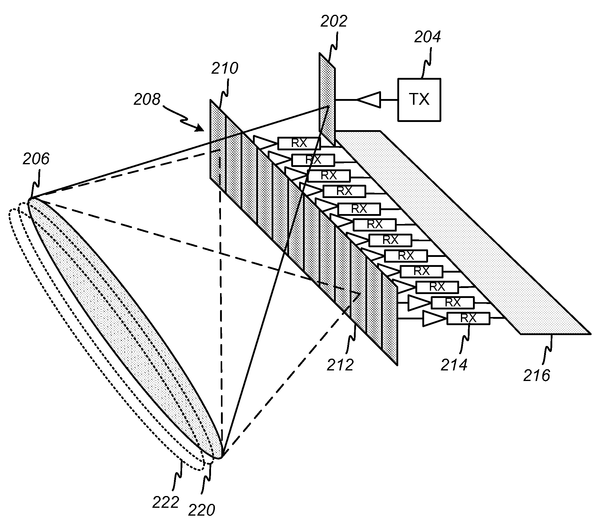
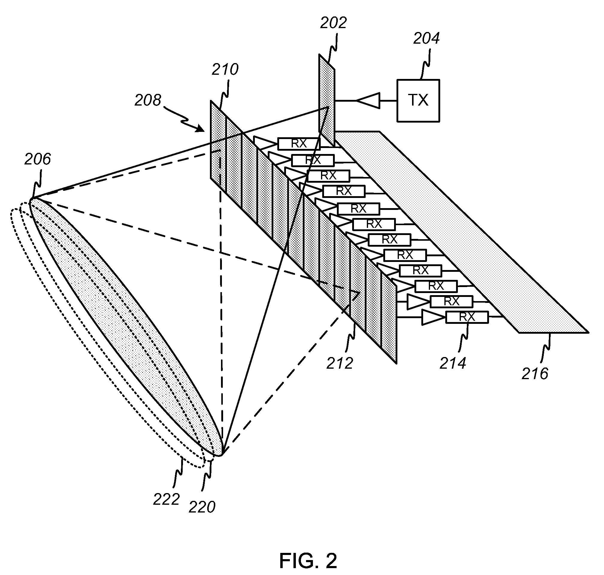
[0024]The invention provides a radar imaging system that directly measures the spatial frequency components of a scene via digital-beam-forming techniques applied along the cross-track dimension. Range gating is used in the along-track dimension to divide the return from an illuminated swath into multiple range bins that may be processed independently. The system provides an improved signal-to-noise ratio and lends significant flexibility to the image formation process, improving the quality of the radar imaging.

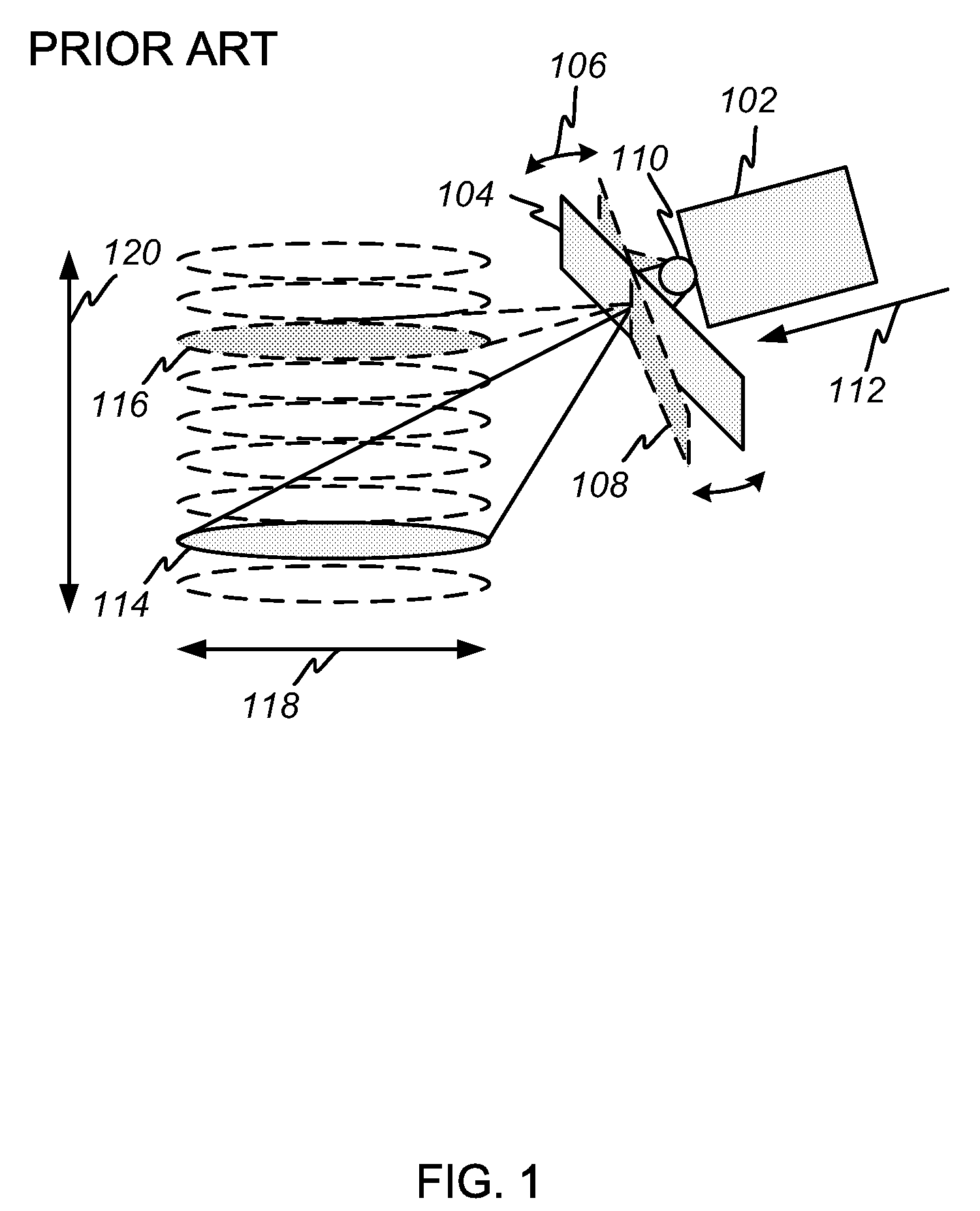
[0025]FIG. 1 depicts a conventional forward-looking vehicle-mounted imaging radar system employing a gimbaled antenna. A vehicle 102 moves in the direction indicated at 112. An antenna 104 is mounted to the front of the vehicle 102 on gimbals 110 that allow the antenna to be moved back and forth in azimuth, as indicated at 106. The antenna 104 is used for both transmit and receive. In transmit, the antenna 104 illuminates a spot 114 on the ground ahead of and below the vehic...


PUM


Abstract

A radar imaging system is provided that directly measures the spatial frequency components of a scene via digital-beam-forming techniques applied along the cross-track dimension. Separate transmit and receive antennas provide increased integration time for the receive function, thus improving the signal-to-noise ratio. A segmented receive antenna is employed and processed as a series of interferometers sensitive to spatial frequency components of the scene corresponding to the separation between pairs of antenna elements. Range gating is used in the along-track dimension to divide the return from an illuminated swath into multiple range bins that may be processed independently. The system provides an improved signal-to-noise ratio and lends significant flexibility to the image formation process, improving the quality of the radar imaging. An embodiment having multiple transmit antennas is also provided that enables the generation of three-dimensional stereoscopic radar images.

Description

RELATED APPLICATION DATA[0001]This application claims the benefit, pursuant to 35 U.S.C. § 119(e), of U.S. provisional application Ser. No. 60 / 930,955, filed May 21, 2007.BACKGROUND OF THE INVENTION[0002]1. Field of the Invention[0003]The present invention relates to forward-looking radar imaging systems. In particular, it relates to radar imaging systems that use digital-beam-forming techniques to measure the spatial frequency components of a scene in the cross-track direction.[0004]2. Description of Related Art[0005]Conventional forward-looking imaging radars are widely used for aircraft-landing and vehicle-navigation applications. In such systems, a mechanically gimbaled antenna aperture is usually mounted on the front of an aircraft or other vehicle, and it is generally used for both transmit and receive functions. The antenna is pointed at a fixed elevation angle toward a spot in front of and below the vehicle. The mechanical gimbals allow the antenna to be scanned azimuthally ...

Claims


Application Information

Patent Timeline
Patent Type & Authority Patents(United States)
IPC IPC(8): G01S13/00
CPCG01S13/89G01S13/90H01Q3/26G01S2013/907G01S2013/9047G01S13/9047G01S13/9043G01S13/9023
Inventor CHANG, DONALD CHIN-DONG
Owner SPATIAL DIGITAL SYST
Why Eureka
Try Eureka