
System and method for mapping an index into an IPv6 address
a mapping system and index technology, applied in the field of computer networks, can solve the problems of increasing the processing time of protocols, reducing the efficiency of intermediate devices, and limited number of available addresses, and achieve the effect of facilitating processing
- Summary
- Abstract
- Description
- Claims
- Application Information
AI Technical Summary
Benefits of technology
Problems solved by technology
Method used
Image

Examples
Embodiment Construction
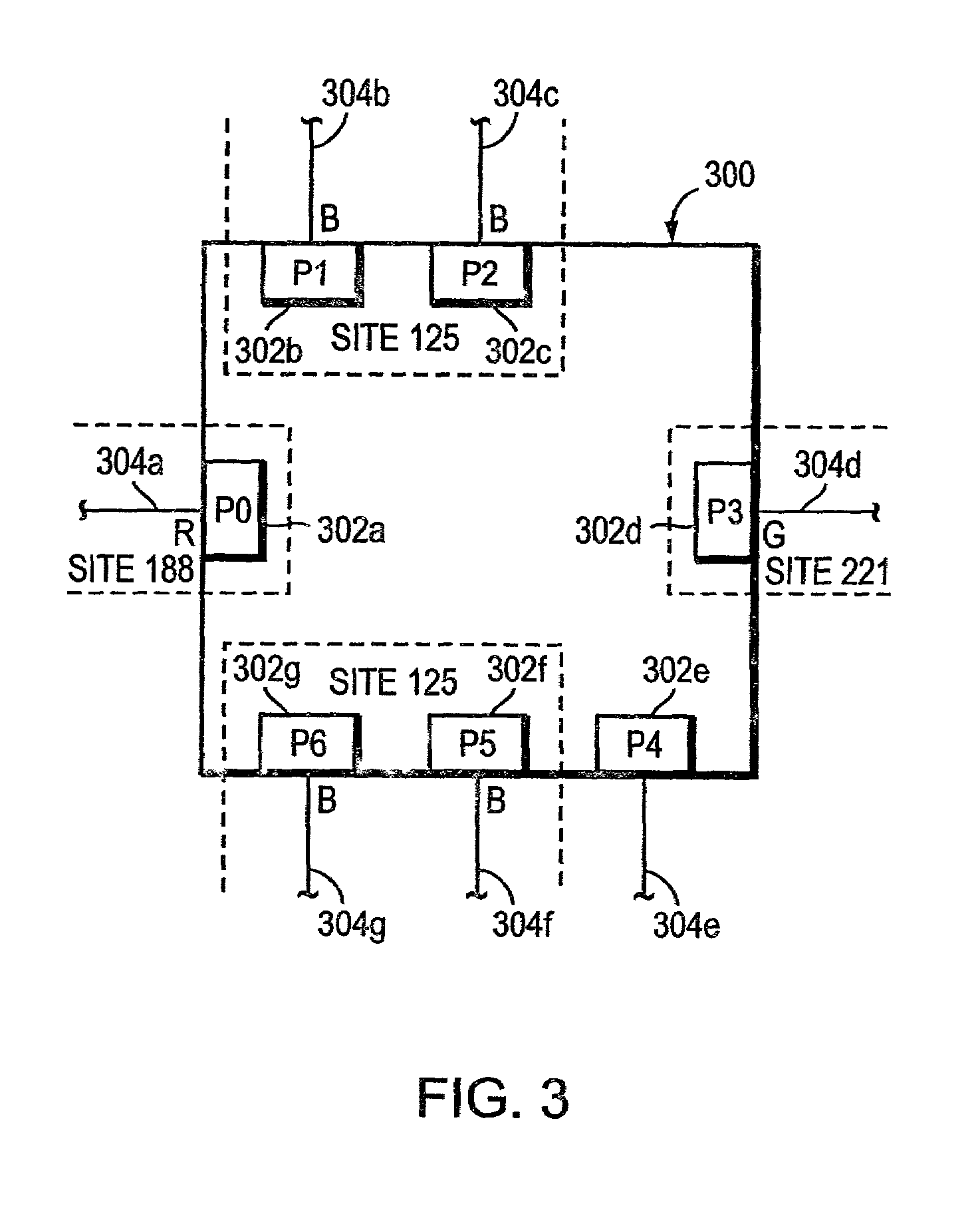
[0029]FIG. 3 is a highly schematic illustration of an intermediate network device 300 in accordance with the present invention. Device 300 includes a plurality of interfaces or ports 302a-g from which network messages can be received and forwarded. Each port, moreover, may be identified by a corresponding port identifier, e.g., P0-P6. Coupled to each port 302a-g is a respective link 304a-g. As described herein, device 300 is configured to forward network messages, e.g., packets and / or frames, originated by a source entity and received by the device 300 on a first port, e.g., P1, onto a second port, e.g., P5 for receipt by a destination entity.
[0030]Device 300 is preferably disposed within a computer network (not shown), and each port or interface of device 300 may be associated with a Virtual Local Area Network (VLAN) designation or identifier (ID) defined within the network. For example, port 302a or P0, which is an access port, is associated with the red (R) VLAN ID, ports 302b, 3...
PUM
 Abstract
Description
Claims
Application Information