
Poled plasma deposition

Inactive Publication Date: 2009-11-03
KUBACKI RONALD M
View PDF3 Cites 2 Cited by
  • Summary
  • Abstract
  • Description
  • Claims
  • Application Information

AI Technical Summary

Problems solved by technology

While this is a straightforward process, there are disadvantages.
One significant disadvantage is the gradual relaxation of the oriented position over time, and hence, instability in the nonlinear characteristics of the film.
Another disadvantage is the multi-step process of: forming the polymer structure; thermal cycling the structure to near glass transition temperature; applying a relatively large electrostatic poling field to the structure; and bringing the polymer structure back to room temperature.

Method used


Image

  • Poled plasma deposition
  • Poled plasma deposition
  • Poled plasma deposition

Examples


Embodiment Construction

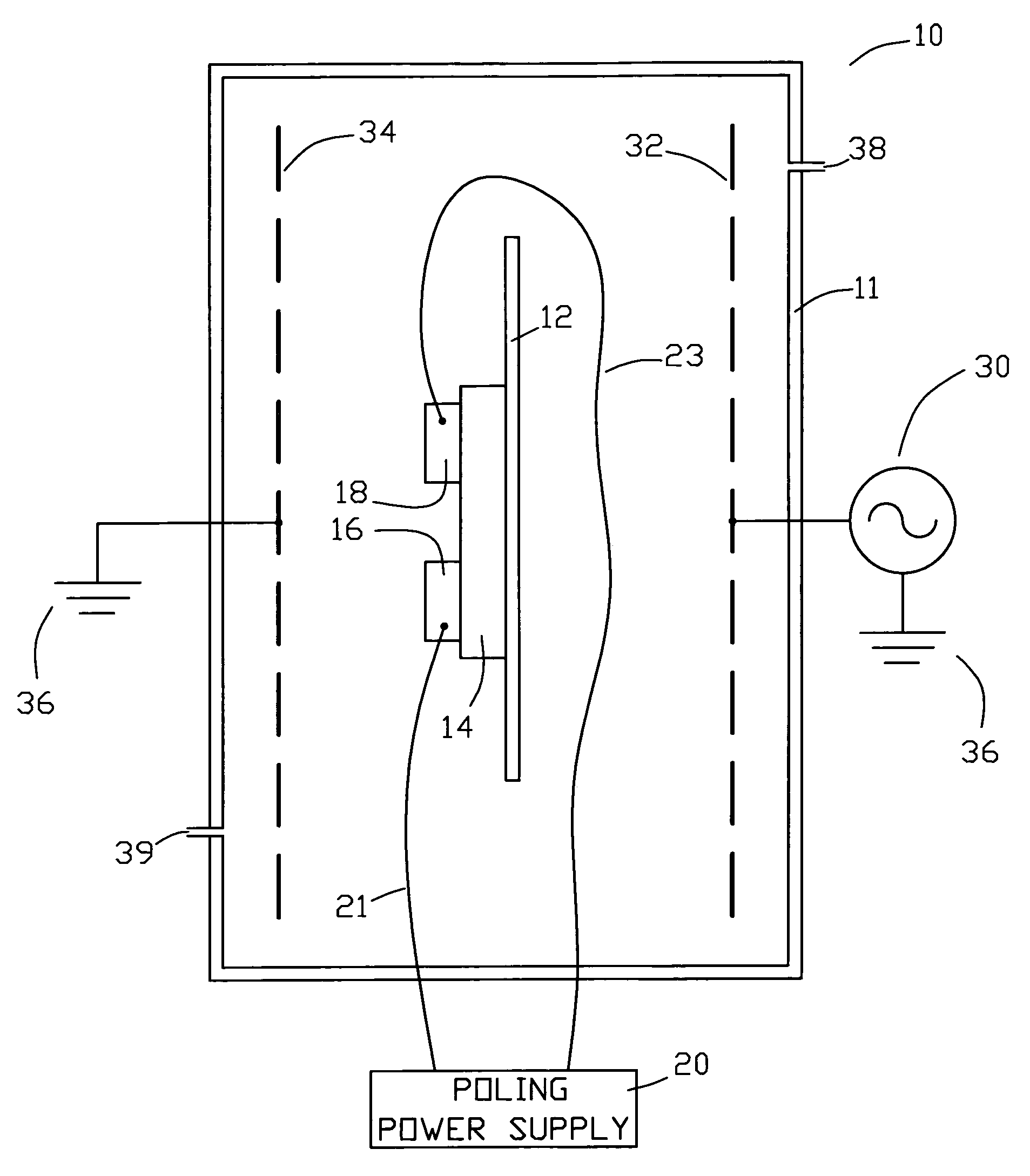
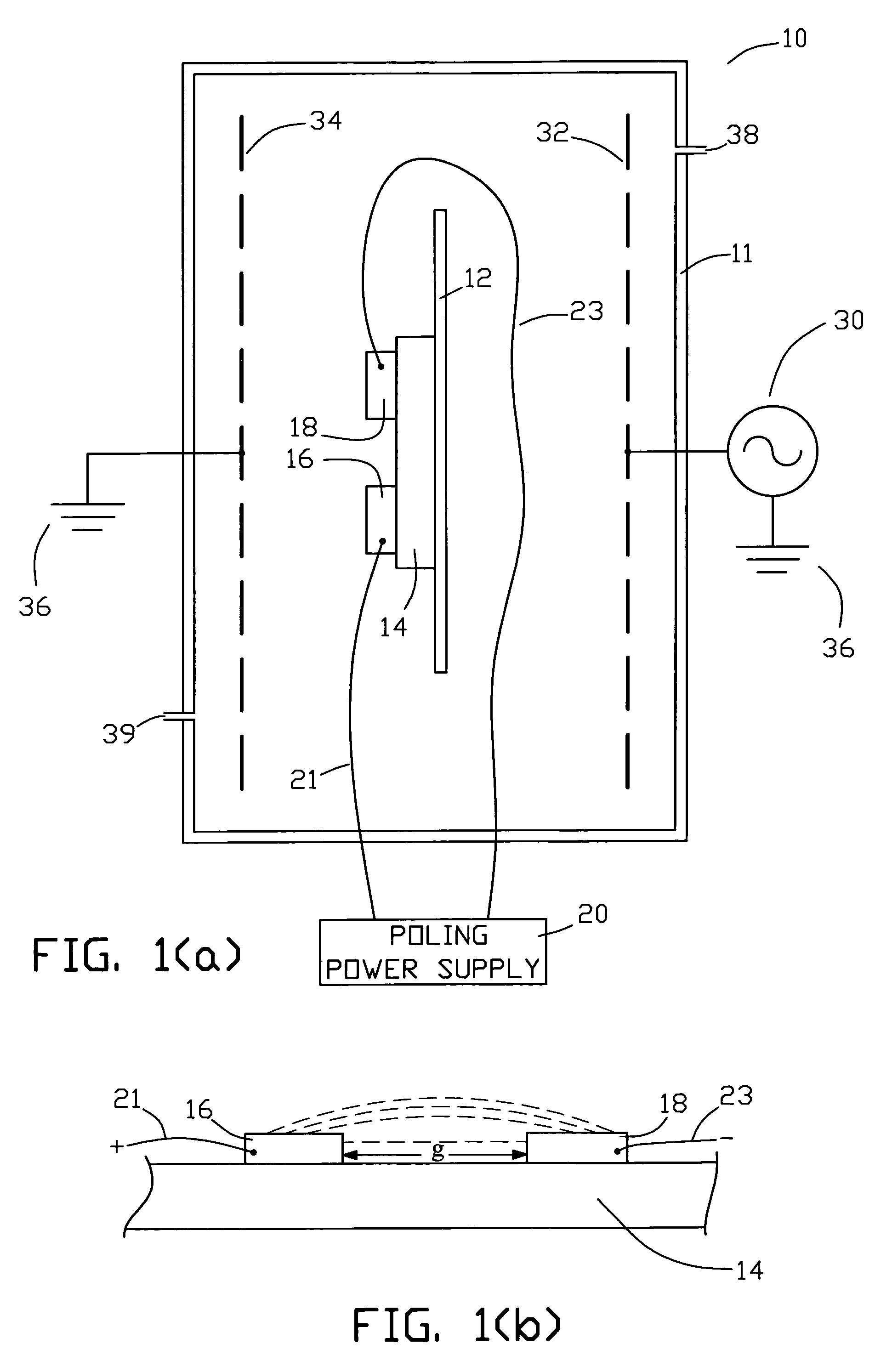
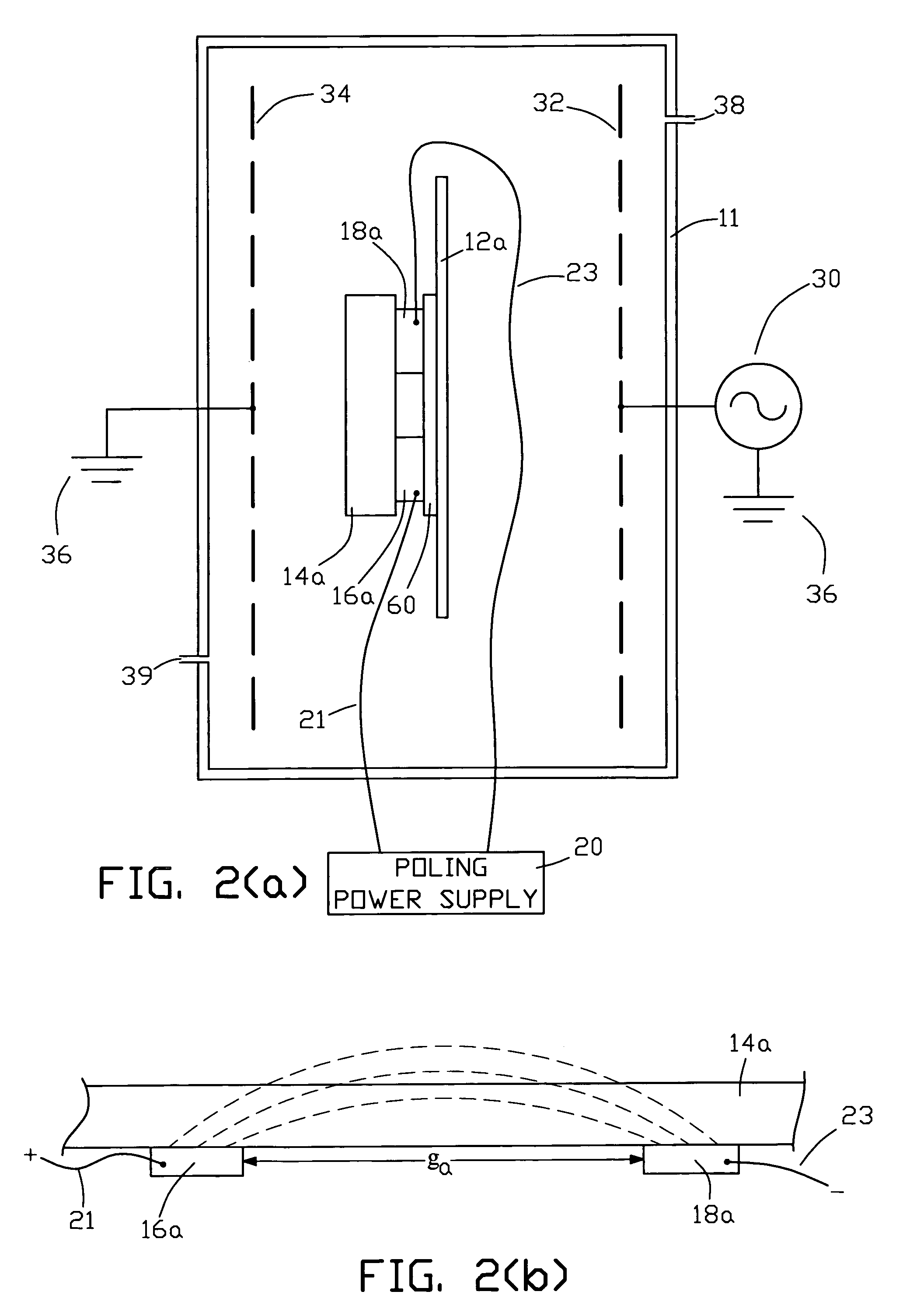
[0017]FIG. 1(a) is a diagrammatic illustration of one example of a plasma deposition reaction and poling chamber system 10 that can be used to perform the poled plasma deposition process of the present invention. Chamber 11 forms a substantially air-tight enclosure in which the plasma deposition and poling is performed in a substantially vacuum environment. Substrate 14 is fixtured in chamber 11. In this example non-limiting example of the invention, platen 12 holds substrate 14 in place within chamber. Positive poling electrode 16 and negative poling electrode 18 are in contact with, or fixed to, substrate 14 in an arrangement that forms a gap between the electrodes. The poling electrodes are suitably connected to dc power source 20 by connectors 21 and 23 via suitable feed throughs in the wall of chamber 11. Plasma excitation power generator 30 (with suitable matching network, if required) provides plasma excitation power to positive plasma-generating electrode 32 via a suitable f...


PUM

PropertyMeasurementUnit
Pressureaaaaaaaaaa
Poweraaaaaaaaaa
Electric potential / voltageaaaaaaaaaa

Abstract

A poled polymer structure is formed on the surface of a substrate by poling a nonlinear optical reactant during a plasma polymerizing deposition of the reactant onto the surface. The substrate is fixed between the positive plasma-generating and ground electrodes in an air-evacuated chamber so that the substrate electrically floats relative to the electrodes. This arrangement permits the application of an electrostatic poling field to the depositing polymer structure while the plasma excitation power is maintained. The electrostatic poling field is produced by the application of a dc voltage to poling electrodes that can be arranged in various configurations relative to the substrate.

Description

CROSS REFERENCE TO RELATED APPLICATIONS[0001]This application is a division of U.S. application Ser. No. 10 / 322,895, filed Dec. 18, 2002, now U.S. Pat. No. 6,767,590, which is incorporated herein by reference in its entirety.FIELD OF THE INVENTION[0002]The present invention relates generally to poled plasma depositions, and in particular, to a deposition wherein a poled polymer structure is formed by applying a poling field during the plasma polymerization process.BACKGROUND OF THE INVENTION[0003]Nonlinear optical devices formed from poled polymer structures are used in numerous applications, such as planar waveguide modulators or second harmonic generators in integrated circuits. Typically the poled polymer structure is fabricated by poling a polymer film after the film has been formed. For example, a polymer film containing chromophores with high polarizabilities can be heated to near its glass transition temperature and subjected to an electrostatic field (poled power supply) to ...

Claims


Application Information

Patent Timeline
IPC IPC(8): C23C16/503C23F1/00C23C16/509H01L21/306C23C16/22B05D7/24G02F1/065G02F1/355
CPCB05D1/62G02F1/3558G02F1/065
Inventor KUBACKI, RONALD M.
Owner KUBACKI RONALD M
Learn More