Thin-film magnetic head having heatsink wider on air bearing surface side

a thin film, magnetic head technology, applied in the direction of magnetic recording, instruments, data recording, etc., can solve the problems of joule heat and heat caused by eddy current loss, heaters are at risk of melting, electrical resistance value of mr read head elements to change, etc., to avoid degradation of reading performance due to the increase in element temperature, the effect of high sensitivity to magnetic fields

Active Publication Date: 2009-11-03
TDK CORPARATION
View PDF5 Cites 18 Cited by
  • Summary
  • Abstract
  • Description
  • Claims
  • Application Information

AI Technical Summary

Benefits of technology

[0016]The pattern width (WSH1) in the track-width direction of an end portion in the ABS side is larger than a pattern width (WSH2) in the track-width direction of the opposite end portion. As the result, the heat reaching the heatsink element from the heating element positioned opposite to the ABS in relation to the magnetic head elements flows selectively to the direction that is mostly toward the upper and lower shield layers and the magnetic pole layer, and the amount of heat dissipated from the surface opposite to the heating element of the heatsink element is reduced. The more heat thereby reaches and expands the neighborhood of the magnetic head elements. Consequently, the conventional problem that most of the heat generated from the heating element is dissipated toward the area other than the neighborhood of the magnetic head elements can be solved, and the protrusion efficiency of these head elements by the heat generated from the heating element is improved.
[0017]Furthermore, by setting the pattern width WSH1 to an enough large value, the heat generated from the write head element is dissipated enough toward the overcoat layer. As the result, a large inductance variation by the thermal expansion of the write head element itself can be avoided.
[0019]By specifying the above-mentioned pattern width and shape of the heatsink element, the heat selectively flowing in the direction toward the upper and lower shield layers and the magnetic pole layer is increased. So the neighborhood of the magnetic head elements can be expanded more positively. Consequently, the protrusion efficiency by the heat of these head elements is more improved.
[0021]By positioning the heating element between the substrate and the heatsink, most of the heat transmitted in the direction opposite to the substrate is received by the heatsink element, and the amount of the heat reaching the neighborhood of the magnetic head element is increased. Consequently, the protrusion efficiency by the heat of these head elements is more improved. And in the case that the heating element is wholly covered with the heatsink element, the amount of the heat received by the heatsink element is more increased. Furthermore, by providing the heat-conduction-controlling layer, most of the heat transmitted to the substrate side from the heating element is prevented from reaching the substrate due to the shielding effect of the heat-conduction-controlling layer. Accordingly, the amount of the heat received by the heatsink element is more increased, and the protrusion efficiency by the heat of these head elements is much more improved.
[0023]In this case, the distance between the heatsink layer and the element-formed surface of the slider substrate becomes the same as that between one layer of the upper and lower shield layers and the magnetic pole layer and the element-formed surface. As the result, the gap between the heatsink layer and the one layer is clearly defined. Moreover, because the constituent material of both layers becomes the same, it becomes easy to design the thermal conduction in the magnetic head elements.
[0025]A current-in-plane GMR (CIP-GMR) element, a current-perpendicular-to-plane GMR (CPP-GMR) element and the TMR element have very high sensitivity to magnetic fields, however their outputs depend strongly on their temperature. Correspondingly, by using these elements as the read head element of the thin-film magnetic head according to the present invention, the degradation of the reading performance due to the increase in the element temperature can be avoided, and these elements with very high sensitivity can be utilized effectively.

Problems solved by technology

However, during writing signals, a Joule heat and a heat caused by eddy-current loss are generated from the inductive write head element.
In the case of the phenomenon, when the designed value of the magnetic spacing dMS is very small, the protruding MR read head element is at risk of contacting the magnetic disk surface, and a frictional heat generated by the contact may cause the electrical resistance value of the MR read head element to change, raising the problem such as an abnormal signal (thermal asperity).
However, in the case with the heat control layer, the heater is at risk of melting due to the increase in the temperature of itself.
However, when the heatsink layer is provided adjacent to the heater, the problem of the decease in the protrusion efficiency of the magnetic head elements by the heat generated from the heater is often happened.
Consequently, the heat generated form the heater does not sufficiently reach the neighborhood of the magnetic head elements, so the thermal expansion that protrudes the magnetic head elements is not satisfactorily generated and the protrusion efficiency is decreased.
Therefore, it is difficult to lower the power consumption of the magnetic disk drive apparatus and to miniaturize the apparatus, which is recently tried to be incorporated into a mobile device such as a cellular phone.

Method used


Image

  • Thin-film magnetic head having heatsink wider on air bearing surface side
  • Thin-film magnetic head having heatsink wider on air bearing surface side
  • Thin-film magnetic head having heatsink wider on air bearing surface side

Examples


Embodiment Construction

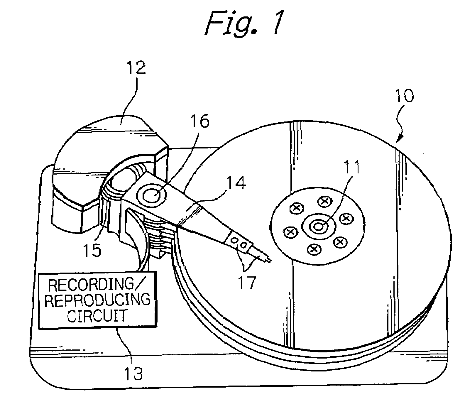
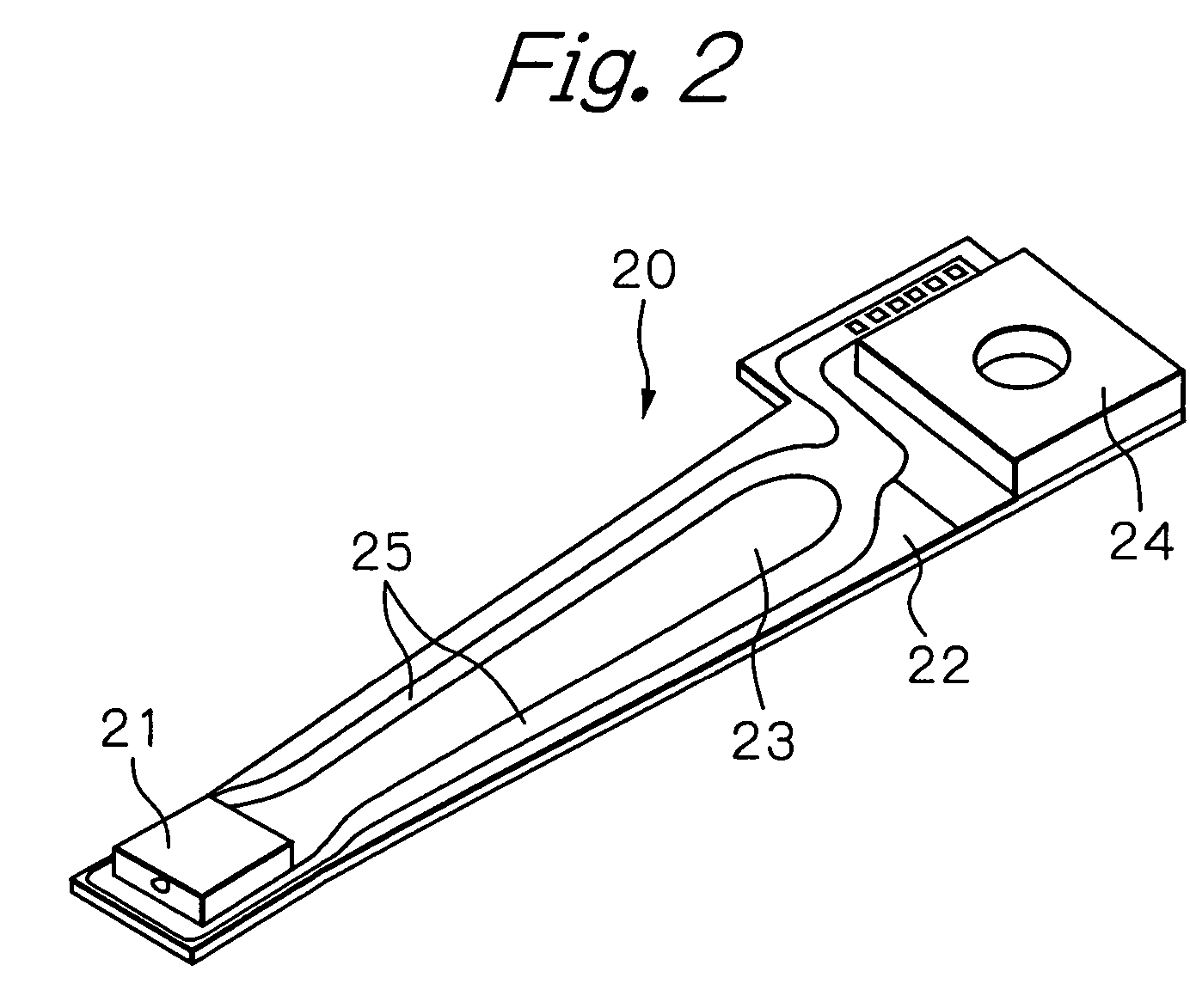
[0044]FIG. 1 shows a perspective view schematically illustrating a structure of a main part of an embodiment of a magnetic disk drive apparatus according to the present invention, FIG. 2 shows a perspective view illustrating an embodiment of an HGA according to the present invention, and FIG. 3 shows a perspective view of an embodiment of a thin-film magnetic head (slider) provided on the end portion of the HGA.

[0045]In FIG. 1, reference numeral 10 indicates a plurality of magnetic disks rotating around a rotational axis of a spindle motor 11, 12 indicates an assembly carriage device for positioning a thin-film magnetic head (slider) on a track, and 13 indicates a recording / reproducing circuit for controlling read / write operations and heat operations of the thin-film magnetic head, respectively.

[0046]The assembly carriage device 12 is provided with a plurality of drive arms 14. These drive arms 14 are rotatable around a pivot bearing axis 16 by means of a voice coil motor (VCM) 15 a...


PUM

PropertyMeasurementUnit
thicknessaaaaaaaaaa
thicknessaaaaaaaaaa
thicknessaaaaaaaaaa

Abstract

A thin-film magnetic head with a higher protrusion efficiency is provided, which comprises: a substrate with an air bearing surface (ABS); a read head element including a lower and upper shield layers, and a write head element including a magnetic pole layer; a heating element provided in a position opposite to the ABS in relation to the read and write head elements; and a heatsink element including a heatsink layer provided adjacent to an end opposite to an end in the ABS side of at least one layer of the lower and upper shield layers and the magnetic pole layer, the heatsink element having a shape that a pattern width in the track-width direction of an end portion in the ABS side is larger than a pattern width in the track-width direction of an end portion opposite to the end portion in the ABS side.

Description

PRIORITY CLAIM[0001]This application claims priority from Japanese patent application No. 2004-294760, filed on Oct. 7, 2004, which is incorporated herein by reference.BACKGROUND OF THE INVENTION[0002]1. Field of the Invention[0003]The present invention relates to a thin-film magnetic head with a heater, a head gimbal assembly (HGA) with the thin-film magnetic head and a magnetic disk drive apparatus with the HGA.[0004]2. Description of the Related Art[0005]In a magnetic disk drive apparatus, when writing or reading signals, a thin-film magnetic head hydrodynamically flies with a predetermined spacing on a rotating magnetic disk. While flying on the magnetic disk, the thin-film magnetic head writes signals to the magnetic disk using magnetic fields generated from an inductive write head element, and reads signals by sensing magnetic fields corresponding to the signals from the magnetic disk through an magnetoresistive (MR) effect read head element. On these occasions, a magnetic spa...

Claims


Application Information

Patent Timeline
Patent Type & Authority Patents(United States)
IPC IPC(8): G11B5/31G11B5/39
CPCG11B5/3106G11B5/3136G11B5/6064G11B5/6005G11B5/314G11B5/607
Inventor KURIHARA, KATSUKIOIKE, TAROHIRABAYASHI, HIRAKUOTA, NORIKAZU
Owner TDK CORPARATION
Why Eureka
Try Eureka