Binary controlled phase selector with output duty cycle correction

a phase selector and binary control technology, applied in the direction of pulse manipulation, transmission monitoring, pulse technique, etc., can solve the problems of voltage spikes on output signals, affecting the integrity of output signals, and instability of output signals

Active Publication Date: 2009-11-03
GLOBALFOUNDRIES US INC
View PDF0 Cites 13 Cited by
  • Summary
  • Abstract
  • Description
  • Claims
  • Application Information

AI Technical Summary

Benefits of technology

[0009]There also is a need for an arrangement that enables a digital phase selection circuit to be implemented in a manner that does not introduce noise spikes or voltage spikes due to transitions in digital values.

Problems solved by technology

Implementation of digital phase shifting systems in an integrated circuit, however, may suffer from numerous problems that may affect the integrity of the signal to be output.
However, reliance on binary coding suffers from the disadvantage of Most Significant Bit (MSB) rollover, where a simultaneous transition in multiple bits due to a change in value (e.g., “7”=0111 to “8”=1000) creates numerous discontinuities in the circuits implementing the digital system, resulting in voltage spikes on the output signal; such voltage spikes may cause transient phase errors that may result in misinterpretation of a clock strobe, data, etc., resulting in errors due to instability of the output signal.
Efforts to filter the voltage spikes from the output signal often are not practical in integrated circuits due to the added delay or the increased capacitance.
In addition, implementation of digital phase shifting systems in an integrated circuit may encounter errors due to nonlinearities due to process variations encountered during manufacture of the integrated circuit.
Finally, digital phase shifting systems may suffer from the problem of adding a bias to the reference clock signal that may affect the duty cycle of the output signal.

Method used


Image

  • Binary controlled phase selector with output duty cycle correction
  • Binary controlled phase selector with output duty cycle correction
  • Binary controlled phase selector with output duty cycle correction

Examples


Embodiment Construction

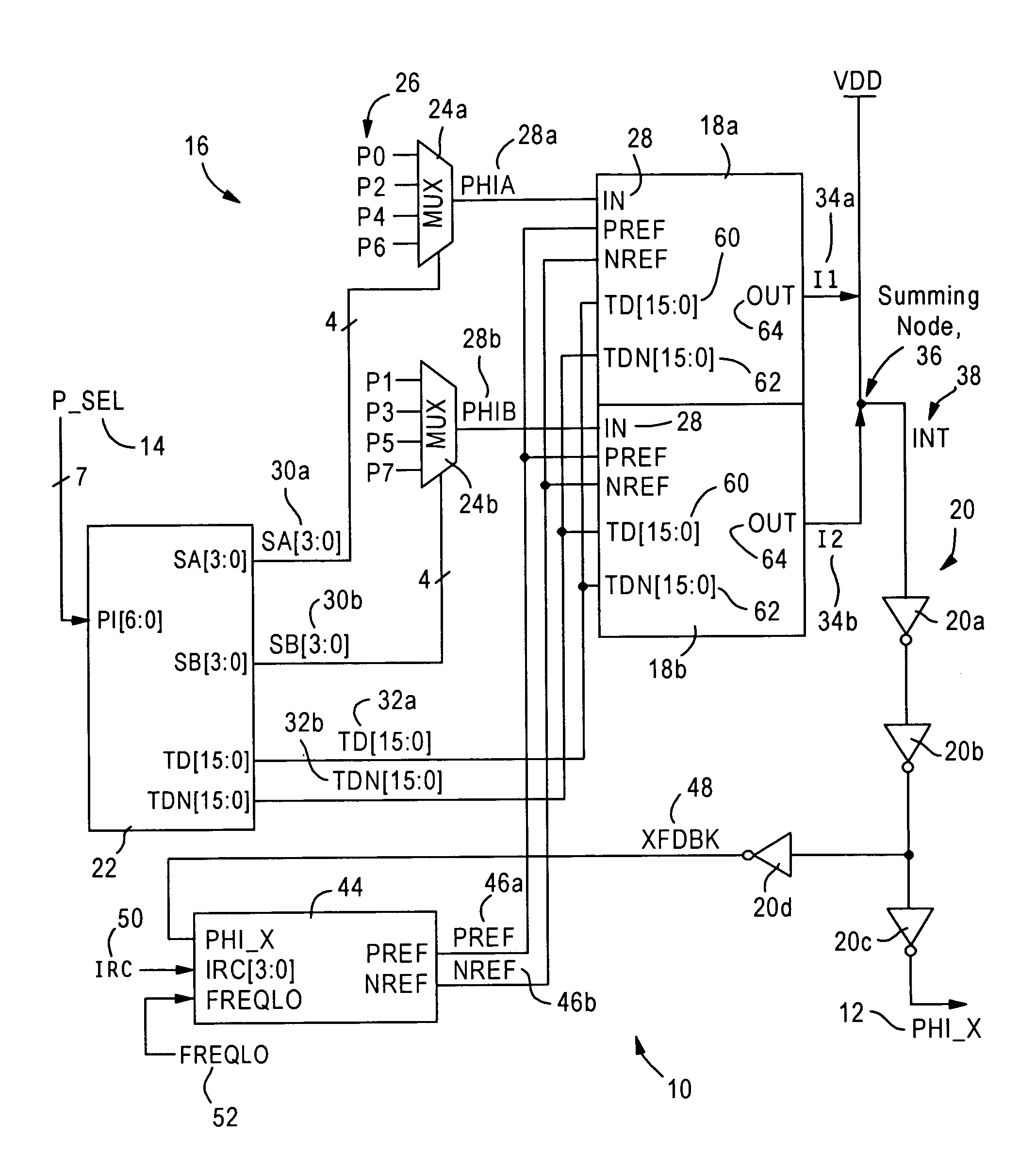
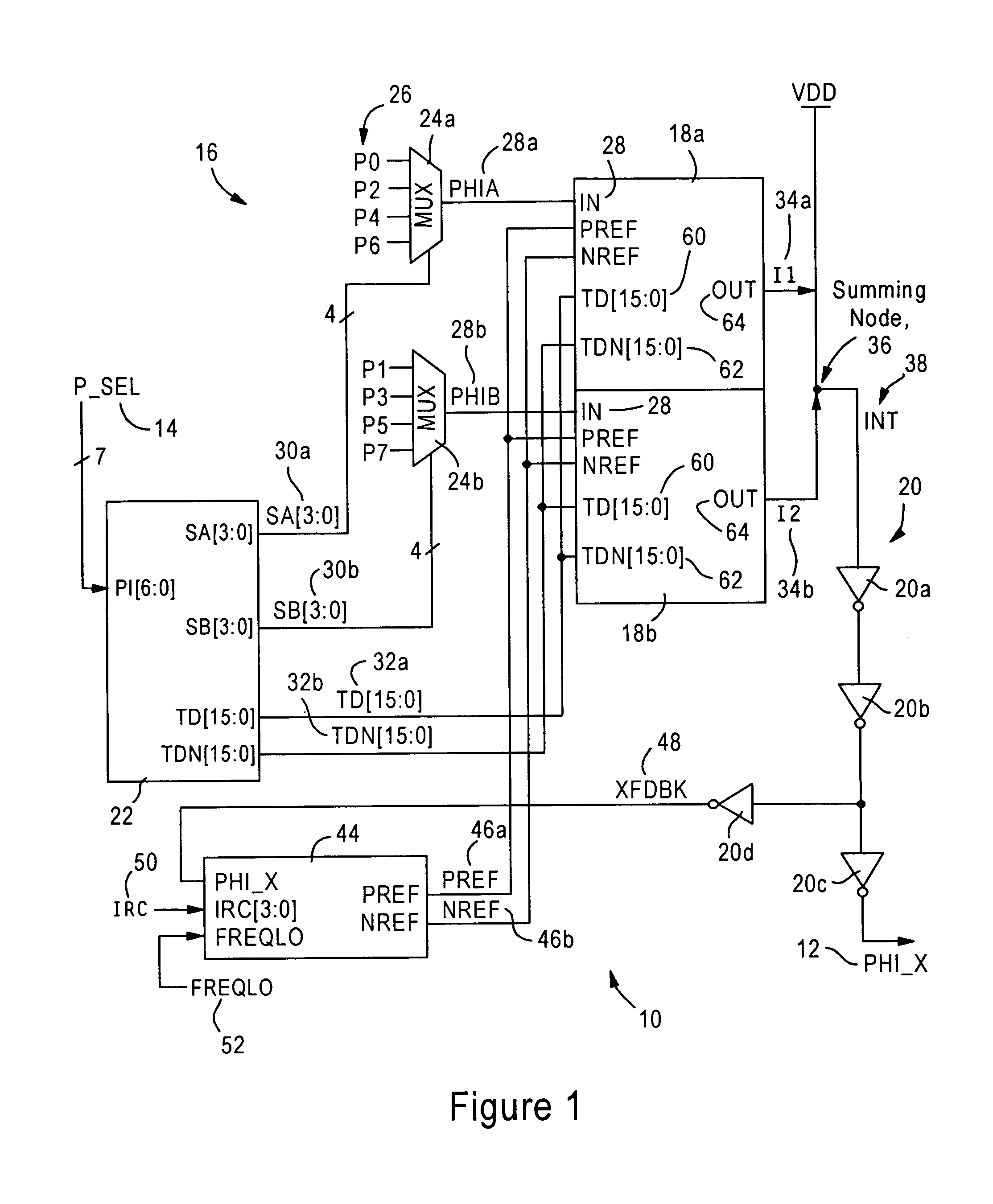
[0022]The disclosed embodiment is directed to an integrated circuit, for example a microprocessor or a device that interfaces with the microprocessor via a high-speed link such as a HyperTransport™ link, having a phase selection circuit for outputting a phase-adjusted clock signal in response to a reference clock and a phase selection value.

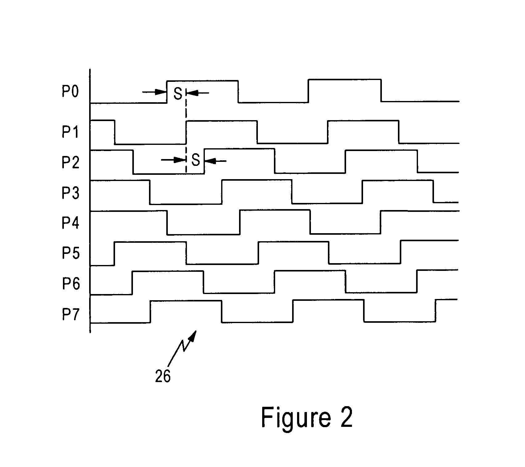
[0023]FIG. 1 is a diagram illustrating a phase selection circuit 10, also referred to as a binary controlled phase generator, configured for generating a clock signal (PHI_X) 12. The phase selection circuit 10 generates the signal 12 to have a selected phase according to a phase selection value (P_SEL) 14, where the phase selection value 14 is a 7-bit digital value that specifies one of 128 available digital phase increments across a period of a single clock cycle.

[0024]As described below, the phase selection circuit 10 is configured for solving the problem of being able to precisely subdivide a reference clock into 128 equally spaced phase posit...


PUM


Abstract

A phase selection circuit having a selection circuit, binary weighted current sources, and an amplifier circuit. The phase selection circuit is configured for selecting adjacent phase signals from a number of equally-spaced phases of a clock signal, based on a phase selection value. The selection circuit outputs the adjacent phase signals to respective first and second binary weighted current sources, along with a digital interpolation value. The first current source outputs a contribution current onto a summing node based on the first adjacent phase signal and the digital interpolation control value, and the second current source outputs a second contribution current to the summing node based on the second adjacent phase signal and an inverse of the digital interpolation control value, resulting in an interpolated signal. An amplifier circuit outputs the interpolated signal as a phase-interpolated clock signal according to the phase selection value.

Description

BACKGROUND OF THE INVENTION[0001]1. Field of the Invention[0002]The present invention relates to digital phase shifting systems configured for outputting a phase-shifted signal relative to a reference clock.[0003]2. Background Art[0004]Newer communications systems require advanced processing of high speed digital signals in order to accommodate precise timing requirements. For example, processor-based communications systems such as HyperTransport™ bus architectures rely on integrated circuits having phase shifting circuits for phase-shifting a clock signal, for example for timing synchronization.[0005]Implementation of digital phase shifting systems in an integrated circuit, however, may suffer from numerous problems that may affect the integrity of the signal to be output. For example, digital systems often rely on binary coding, where a digital value composed of N bits has a range of values from zero to 2N−1. However, reliance on binary coding suffers from the disadvantage of Most...

Claims


Application Information

Patent Timeline
Patent Type & Authority Patents(United States)
IPC IPC(8): H04L7/00
CPCH03K5/135H03K2005/00286H03K2005/00058H03K2005/00052
Inventor TALBOT, GERALD ROBERT
Owner GLOBALFOUNDRIES US INC
Why Eureka
Try Eureka