Complex system of vegetation and solar cell

a solar cell and complex technology, applied in the field of complex systems of vegetation and solar cells, can solve the problems of high cost of fixing a solar cell system to a high-rise building, the effect of the shadows of plants and solar cells as well as the maintenance of the solar cell system, and the large area of glass plates occupying a large amount of the weight of the solar cell module, so as to achieve reliable and straightforward execution, excel in terms of economy and reliability, and reliable and straightforward execution

Inactive Publication Date: 2009-11-10
KANEKA CORP
View PDF10 Cites 13 Cited by
  • Summary
  • Abstract
  • Description
  • Claims
  • Application Information

AI Technical Summary

Benefits of technology

[0009]In view of the current situation, the present invention proposes an installation method that makes it possible to install plants and solar cells together on substantially the same plane by providing a mount installation structure that resolves problems related to maintenance and the effect of the shadows of both plants and solar cells, obviates the need for such localized waterproofing of the roof surface, which is costly and labor-intensive, and makes it possible to prevent a reduction in the long-term durability of measures to prevent the solar cell module dropping as a result of a regular load and slight fluctuations and so forth as well as blow-up close to the center of the mount.
[0010]As a result of intensive research, the present inventors found the following means. That is, a vegetation and solar cell complex system of a first aspect of the present invention involves a vegetation and solar cell complex system that installs a solar cell system and plant group together on the same roof surface, wherein the average height, from the roof surface, of the light-receiving surface of a solar cell module is greater than the average height of the plant group and is therefore able to resolve obstructions to the light received by the solar cell that arise from plant shadows.

Problems solved by technology

However, even though the reception of solar light by plants and solar cells is a requirement for the production of the effect, these methods are installation methods in which at least the amount of light received in either case is small and an installation method that installs plants and solar cells together on substantially the same plane has not been proposed.
It may be surmised that the problems of the effect of the shadows of the plants and solar cells as well as maintenance have not been resolved.
Therefore, one may surmise that the method of fixing a solar cell system to a high-rise building is a factor in high costs.
Therefore the large-area plate-like glass plate occupies much of the weight of the solar cell module and is fairly heavy.
However, in this method, the roof surface sustains damage as a result of driving the anchor into the roof surface and there is therefore the risk of a drop in long-term waterproofing properties.
However, there is then the problem of the costs and labor involved in the waterproofing.
However, maintenance mainly for the purposes of waterproofing such as re-covering the waterproof sheet must be performed at regular intervals on the roof comprising the roof surface and there has been the problem that it is not possible to temporarily remove the solar cell system in the bonding that involves such bonding of the concrete foundation to the roof surface via the adhesive.
However, when the mount is fixed to the roof surface by means of wire, in order to render the attachment angle an angle that is close to the perpendicular, the position in which the wire is fixed cannot be spaced far from the mount and, therefore, ultimately, there is a need to erect an anchor bolt in the roof installation surface and the waterproof surface must be damaged.
In addition, another problem with this method that has been cited is that, when the surface area of the mount is large, blow-up close to the center of the mount cannot be prevented by fixing only the periphery of the solar cell module by means of wire.
In this case, because the load of the wind pressure on the solar cell module is supported by the wire, a wire draw strength that is regularly high is required and slight fluctuations caused by the wind pressure load are unavoidable and there is a problem with long-term durability resulting from metal fatigue of the wire main body and attachment portion.
Further, when the surface area of the mount increases, the above problems are exacerbated.
With this method, there is sometimes a problem with the waterproof structure of the penetration part due to the act of securing the mount attachment load by means of the anchor bolt that penetrates the roof surface via wire.
Further, when the solar cell module is bonded after being fixed with wire, it is difficult to firmly and uniformly bond at all points and, when an excessive load is applied, there is the possibility of damage to weak points.

Method used


Image

  • Complex system of vegetation and solar cell
  • Complex system of vegetation and solar cell
  • Complex system of vegetation and solar cell

Examples


first embodiment

[0044]Embodiments of the present invention will be described in detail hereinbelow with reference to the attached drawings. First, the present invention will be described based on FIGS. 1 to 6.

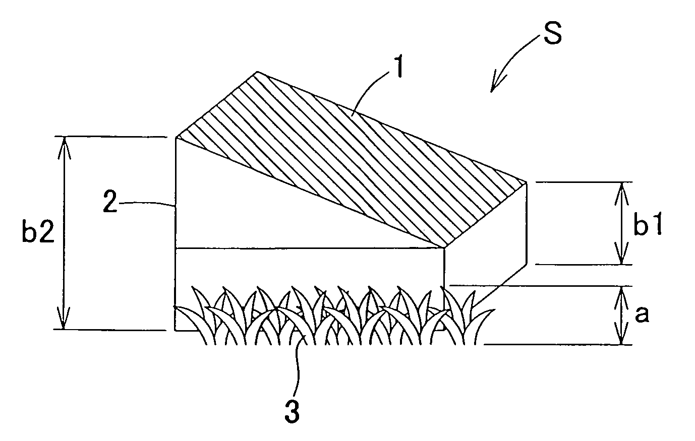
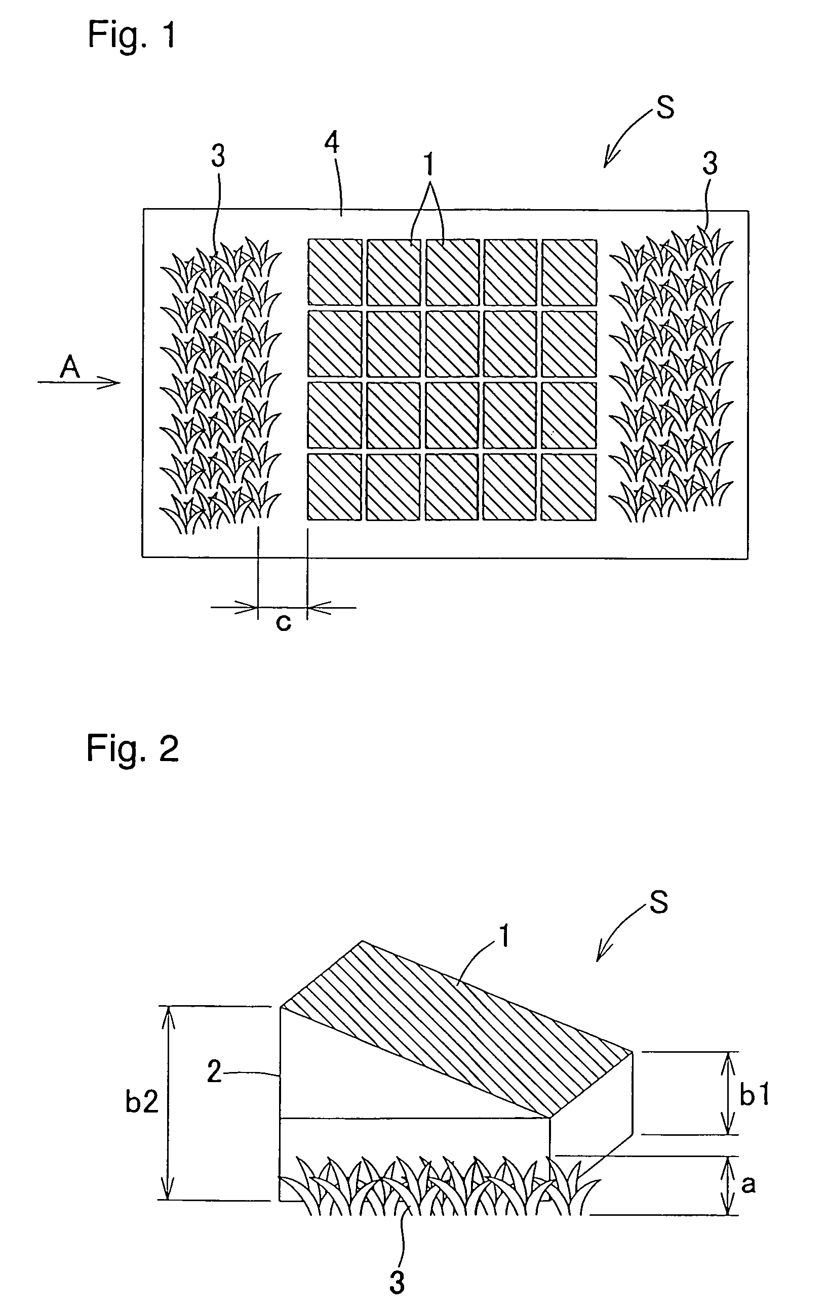
[0045]As shown in FIGS. 1 and 2, a vegetation and solar cell complex system S of this embodiment is a system that installs a solar cell system 10 and a plant group 3 together on the same roof surface 4 and the average height b from the roof surface 4 of the light-receiving surface of a solar cell module 1 is greater than the average height a of the plant group 3.

[0046]Here, ‘roof’ indicates a roof of an architectural structure including that of a building or house or the like. However, in order to maximize the effects of the present invention, a roof, that is, a roof surface with a small gradient is preferable.

[0047]‘Plant group 3’ denotes one or more types of plant or two or more types of plant. Example of plants include trees such as broadleaf trees, evergreen trees, deciduous trees, conifer...

second embodiment

[0062]the present invention will be described next with reference to FIG. 7.

[0063]The vegetation and solar cell complex system S of this embodiment is one in which the mount 2 is installed on the same roof surface 4 and a solar cell system rendered by fixing the solar cell module 1 to the mount and a plant group are installed together such that at least the side of the mount 2 and the plant group 3 substantially adjoin one another. Further, the plant group 3 is established to cover half or more of the area that can be ventilated of a mount side 20 and the wind pressure acting on the solar cell system is reduced by the plant anti-wind pressure.

[0064]The arrangement of the solar cell system 10 and the plant group 3 of this embodiment is the same as that in FIG. 1 of the first embodiment. FIG. 7 is a partial view on arrow in the direction of arrow A that serves to illustrate the side of the frame and the area that can be ventilated of the side of the frame, and the frame side 20 shows ...

third embodiment

[0069]the present invention will be described next on the basis of FIGS. 8 to 10.

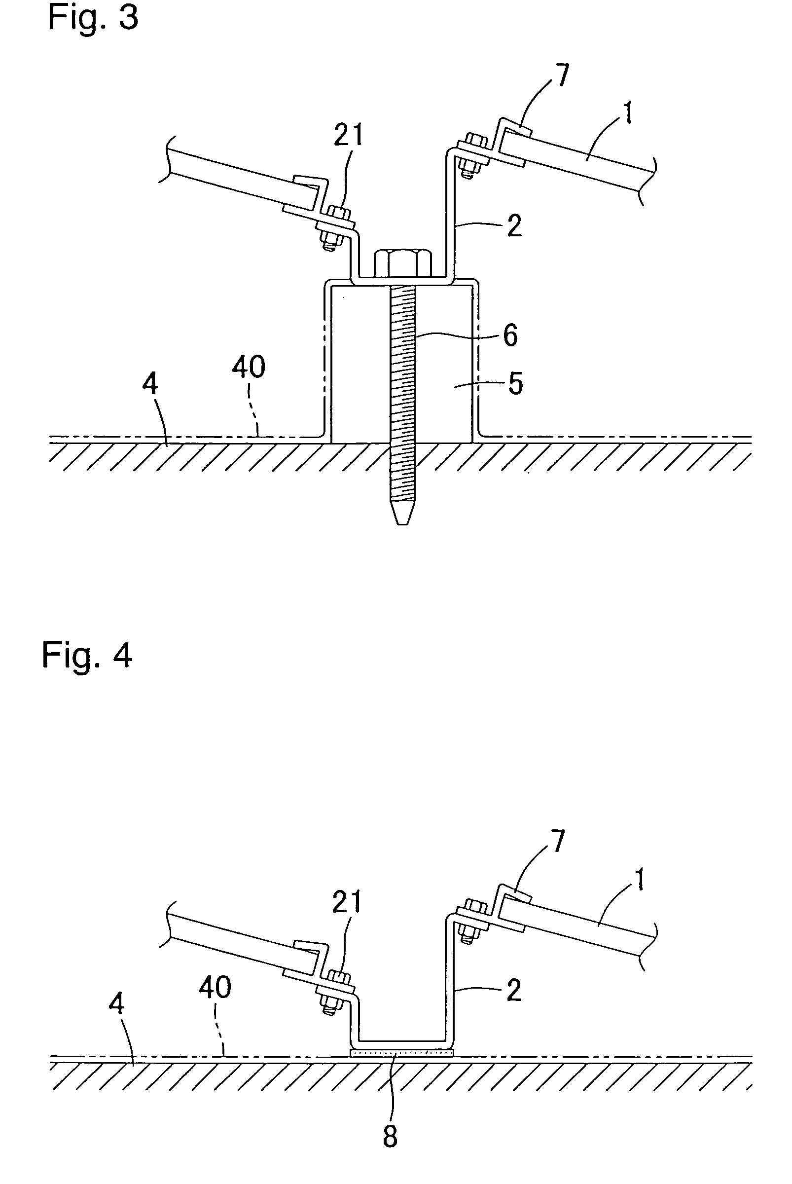
[0070]As shown in FIGS. 8 and 9, the vegetation and solar cell complex system S of this embodiment is constituted such that the mount 2 for fixing the solar cell module 1 is fixed to the roof surface 4 by means of pressure-sensitive adhesive tape 80 and is prevented from dropping by means of wires 9. More specifically, the wires 9 are arranged to pass through gaps 22a that exist in parallel to the roof surface 4 of the mount 2 and more reliably prevent the solar cell module 1 from dropping to the periphery of the roof even in the event of a typhoon or earthquake or the like.

[0071]The mount 2 comprises a mount rail 23 and a pedestal 22 and the solar cell module 1 is stacked on the mount 2. The mount rail 23 is fixed onto the pedestal 22 by means of bolts and the solar cell module 1 is stacked on the mount rail 23. Thereupon, the timely insertion of a sheet consisting of hard rubber as a spacer between th...


PUM


Abstract

A complex system where a plant group having a heat island phenomenon suppression effect and a solar cell having a carbon dioxide generation suppression effect are installed together. The purposes are to eliminate an adverse influence of both shadows of the plant group and the solar cell and to prevent the solar cell system from flying away by the wind pressure against the base side. The average height of the solar cell module is greater than that of the plant group. The plant group and the solar cell module are installed with a gap larger than the distance corresponding to the height difference between them. At least between the paired plant group and solar cell which face each other, an area for a person to walk through is provided. More than half of the ventilation area of the base side is covered with the plant group, a heat insulating material, and a moisture-retaining material.

Description

BACKGROUND OF THE INVENTION[0001]1. Field of the Invention[0002]The present invention relates to a complex system of vegetation and a solar cell in which a plant group having a heat island phenomenon suppression effect and a solar cell having a carbon dioxide generation suppression effect are installed together.[0003]2. Description of the Related Art[0004]Greenification, which involves planting plants on the roofs of structures such as buildings in order to suppress the heat island phenomenon of densely populated urban areas that has become a problem in recent years, is being implemented nowadays. Further, solar cells, which do not involve fossil fuels, that is, which constitute a power-generation technology with a low environmental load without involving the generation of carbon dioxide, have been put to practical use. As a method that installs plants and solar cells together, a method that installs plants on the roof of a building and solar cells on the walls thereof has been disc...

Claims


Application Information

Patent Timeline
Patent Type & Authority Patents(United States)
IPC IPC(8): A01G9/02A01G1/00
CPCA01G1/00F24J2/5239F24J2/5245H02S20/00Y02B10/12Y02E10/47Y02E10/50F24J2002/0084H02S20/23H02S20/10F24S25/61F24S2020/16F24S25/16Y02B10/10
Inventor NOMURA, TAKUJINITTA, YOSHITERUTAJIMA, TSUNEOIMAI, TAKAYOSHIKOJIMA, TOORUSAKAMOTO, AKIHIROHASHIMOTO, TAKUJI
Owner KANEKA CORP
Why Eureka
Try Eureka