Spectroscopic ellipsometer and polarimeter systems
What is AI technical title?
AI technical title is built by PatSnap AI team. It summarizes the technical point description of the patent document.
a technology of ellipsometer and polarimeter, which is applied in the direction of interferometric spectrometry, optical radiation measurement, instruments, etc., can solve the problems of increased heat production and accompanying production of ozone levels to which personnel cannot be safely exposed, unacceptably distributed produced ozone into surrounding atmosphere, and rotating compensator ellipsometer systems do not demonstrate “dead spots”
Inactive Publication Date: 2009-11-10
J A WOOLLAM CO
View PDF58 Cites 110 Cited by
Summary
Abstract
Description
Claims
Application Information
AI Technical Summary
This helps you quickly interpret patents by identifying the three key elements:
Problems solved by technology
Method used
Benefits of technology
Benefits of technology
[0203]Further, at least one of the elements can comprise a mechanism for translating and / or tilting at least one of the elements with respect to another element, for the purpose of aligning the elements of the system so as to reduce deviation between the locus of an output beam as compared to that of a beam input to said system.
[0256]A preferred means for allowing produced ultravioletradiation to exit as a collimated beam comprises a pin hole and lens means present inside a protective tube which serves to prevent air flow by said lens means.
Problems solved by technology
A problem inherent in operation, however, is that to increase intensity output therefrom or extend the useable wavelength range lower limit to say 220 nm or even 160 nm and below, results in increased heat production and accompanying production of levels of ozone to which personnel can not be safely exposed.
The temperature of the source can be controlled by flowing a gas therearound to dissipate increased heat, but this also serves to unacceptably distribute produced ozone into surrounding atmosphere when it is produced.
It is noted that rotating compensator ellipsometer systems do not demonstrate “dead-spots” where obtaining data is difficult.
They can read PSI and DELTA of a material system over a full range of degrees with the only limitation being that if PSI becomes essentially zero (0.0), one can't then determine DELTA as there is not sufficient PSI polar vector length to form the angle between the PSI vector and an “X” axis.
Method used
Image
Click on the blue label to locate the original text in one second.
Reading with bidirectional positioning of images and text.
Examples
Embodiment Construction
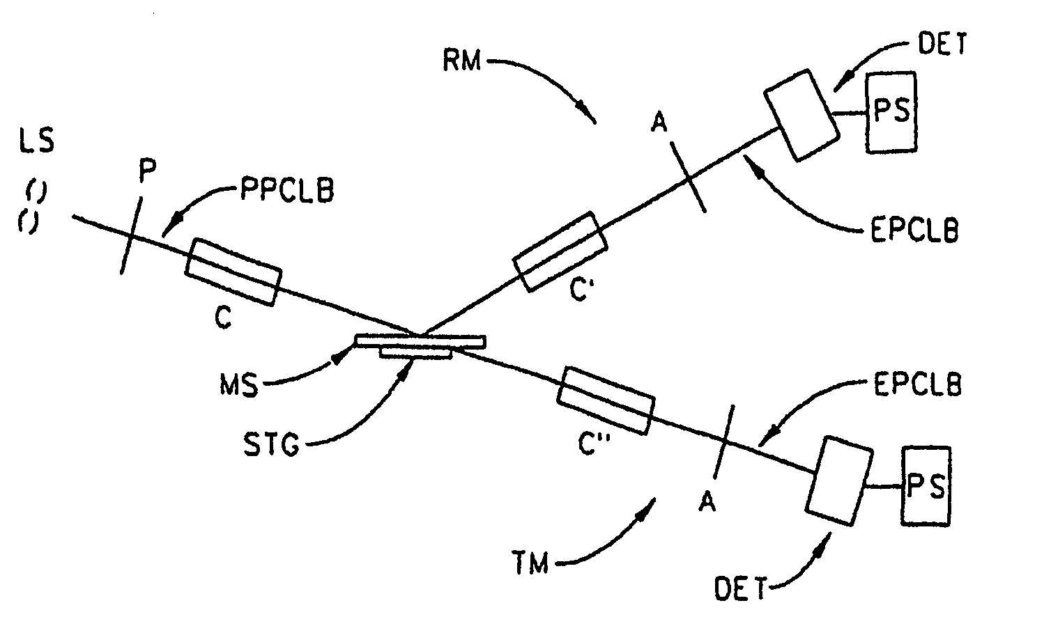
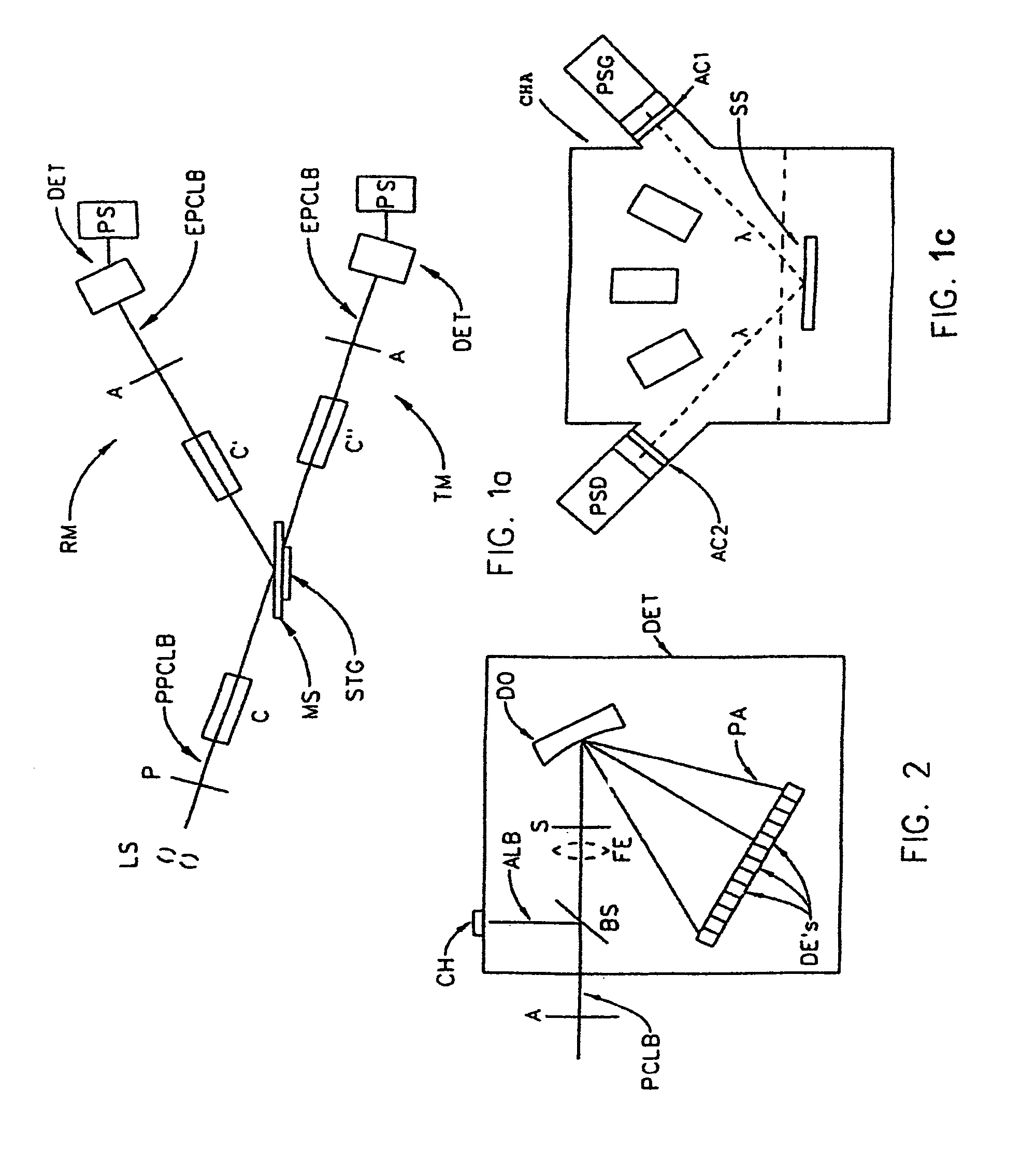
[0321]Referring now to FIG. 1a, there is demonstrated a Material System Investigation System, (ie. a Spectroscopic Ellipsometer System), with provision to investigate a Material System (MS) in either a Reflection Mode (RM) or a Transmission Mode (TM). It is to be noted that said Material System investigation System is generally comprised of a Source of a Polychromatic Beam of Electromagnetic Radiation (LS), (ie. a Broadbandelectromagnetic radiation source), a Polarizer Means (P), a Material System, supporting Stage (STG), an Analyzer Means (A) and a Detector Elements (DE's) containing Photo Array Detector Means System (DET). Also note, however, that FIG. 1a shows Reflection Mode System Compensator(s) Means (C) and (C′) and Transmission Mode System Compensator(s) Means (C) and (C″) as present. It is to be understood that a Compensator Means can be placed ahead of, and / or after a Material System (MS) supporting Stage (STG) in either a Reflection Mode or Transmission Mode System. That...
PUM
Abstract
A rotating compensator spectroscopic ellipsometer or polarimetersystem having a source of a polychromatic beam of electromagnetic radiation, a polarizer, a stage for supporting a material system, an analyzer, a dispersive optics and a detectorsystem which comprises a multiplicity of detector elements, the system being functionally present in an environmental control chamber and therefore suitable for application in wide spectral range, (for example, 130-1700 nm). Preferred compensator design involves a substantially achromatic multiple element compensator systems wherein multiple total internal reflections enter retardance into an entered beam of electromagnetic radiation, and the elements thereof are oriented to minimize changes in the net retardance vs. the input beam angle resulting from changes in the position and / or rotation of the system of elements.
Description
[0001]This Application is a CIP of application Ser. No. 11 / 284,213 filed Nov. 22, 2005, (now U.S. Pat. No. 7,245,376), and therevia this Application is a CIP of 11 / 085,450 Filed Mar. 22, 2005, (now U.S. Pat. No. 7,317,530), which is a CIP of 10 / 928,429 Filed Aug. 27, 2005, (now U.S. Pat. No. 7,317,529), which claims Benefit of 60 / 498,479 Filed Aug. 28, 2003. Via the 11 / 284,213 Application, this Application is also a CIP of application Ser. No. 11 / 103,229 filed Apr. 12, 2005, (now U.S. Pat. No. 7,215,424), and therevia is also a CIP of 10 / 928,429 filed Aug. 27, 2004, which claims benefit of 60 / 498,479 filed Aug. 28, 2003 and therevia is a CIP of application Ser. No. 10 / 669,540 filed Nov. 1, 2003. (now U.S. Pat. No. 7,158,231), which is a CIP of application Ser. No. 10 / 034,800 filed Dec. 28, 2001, (now U.S. Pat. No. 6,822,738), and therevia is a CIP of 09 / 945,962 filed Sep. 4, 2001 now U.S. Pat. No. 7,075,649 and 09 / 496,011 filed Feb. 1, 2000 (now U.S. Pat. No. 6,353,477), which is a ...
Claims
Application Information
Patent Timeline
Application Date:The date an application was filed.
Publication Date:The date a patent or application was officially published.
First Publication Date:The earliest publication date of a patent with the same application number.
Issue Date:Publication date of the patent grant document.
PCT Entry Date:The Entry date of PCT National Phase.
Estimated Expiry Date:The statutory expiry date of a patent right according to the Patent Law, and it is the longest term of protection that the patent right can achieve without the termination of the patent right due to other reasons(Term extension factor has been taken into account ).
Invalid Date:Actual expiry date is based on effective date or publication date of legal transaction data of invalid patent.

