Control circuit having programmable waveform for limiting output power of power converter

a control circuit and power converter technology, applied in the direction of electric variable regulation, process and machine control, instruments, etc., can solve the problems of significant power consumption, affecting the maximum output power, and affecting the selection of components and pcb layout, so as to simplify the pcb layout, reduce power consumption, and shrink the size of the power converter

Active Publication Date: 2009-11-10
SEMICON COMPONENTS IND LLC
View PDF8 Cites 17 Cited by
  • Summary
  • Abstract
  • Description
  • Claims
  • Application Information

AI Technical Summary

Benefits of technology

[0021]The invention provides a control circuit having a programmable waveform for the output power limit of a power converter. The control circuit comprises a switch coupled to a transformer for switching the transformer. An oscillation circuit is used for generating an oscillation signal. A first circuit generates a control signal to control the switch in response to the oscillation signal and a feedback signal for regulating the output of the power converter. A second circuit generates a waveform signal in accordance with the oscillation signal to control the control signal and limit the output power of the power converter. A resistor is coupled to the second circuit to program the waveform of the waveform signal. By properly selecting the resistance of the resistor can achieve an identical output power limit of the power converter for the low line and high line voltage input. Advantageously, the control circuit of the present invention can provide a programmable compensation for the output power limit of the power converter. Therefore, no resistor is needed to apply to sensing the line voltage for the feed-forward compensation, which reduces the power consumption, simplify the PCB layout, and shrinks the size of power converter.

Problems solved by technology

Furthermore, the maximum output power is also affected by the delay time tD of the control circuit.
However, the resistor 20 causes the significant power consumption, especially in high line voltage input.
Besides, the high voltage existing in the resistor 20 causes the drawback for the component selection and a PCB layout.

Method used


Image

  • Control circuit having programmable waveform for limiting output power of power converter
  • Control circuit having programmable waveform for limiting output power of power converter
  • Control circuit having programmable waveform for limiting output power of power converter

Examples


Embodiment Construction

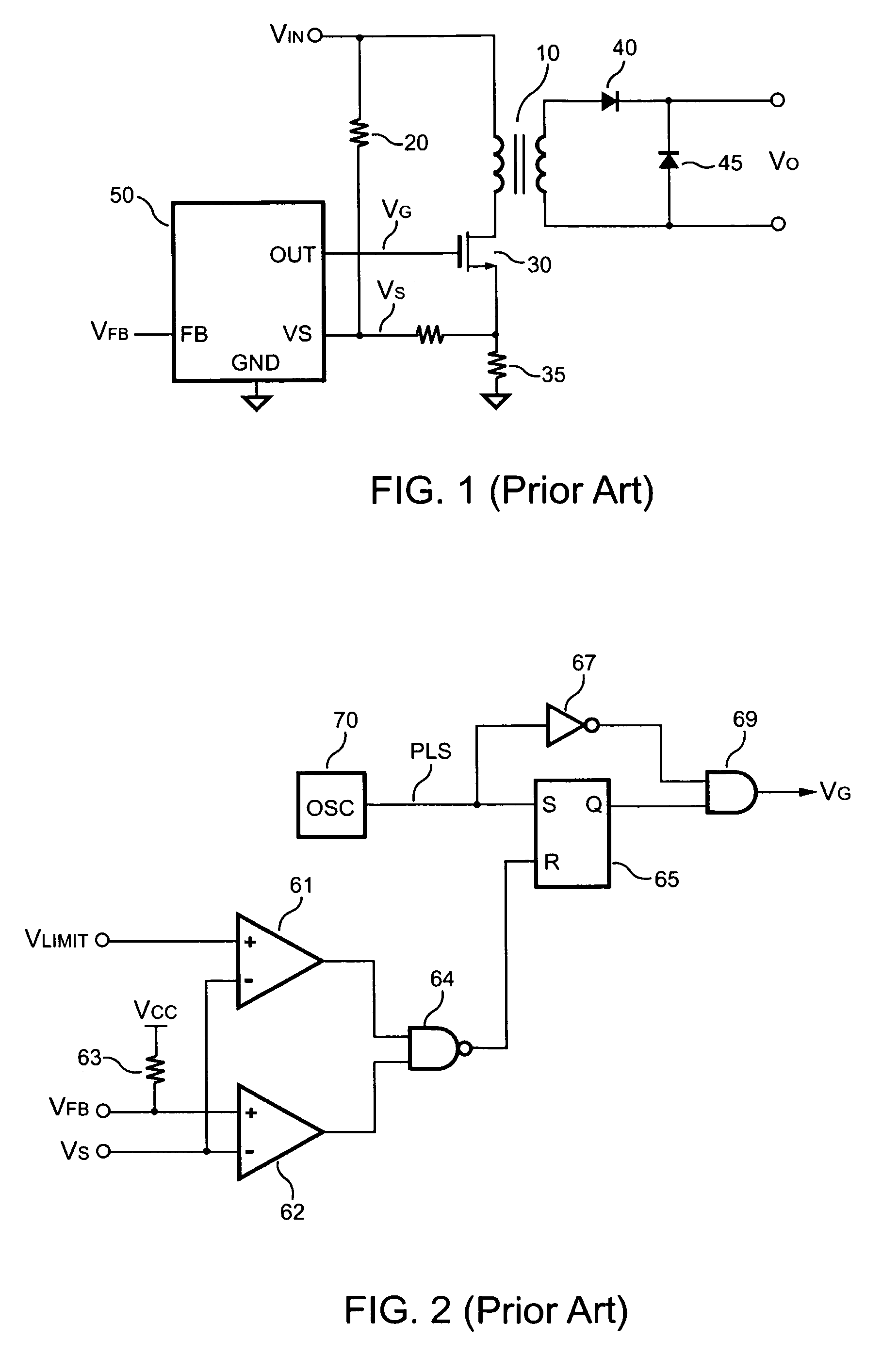
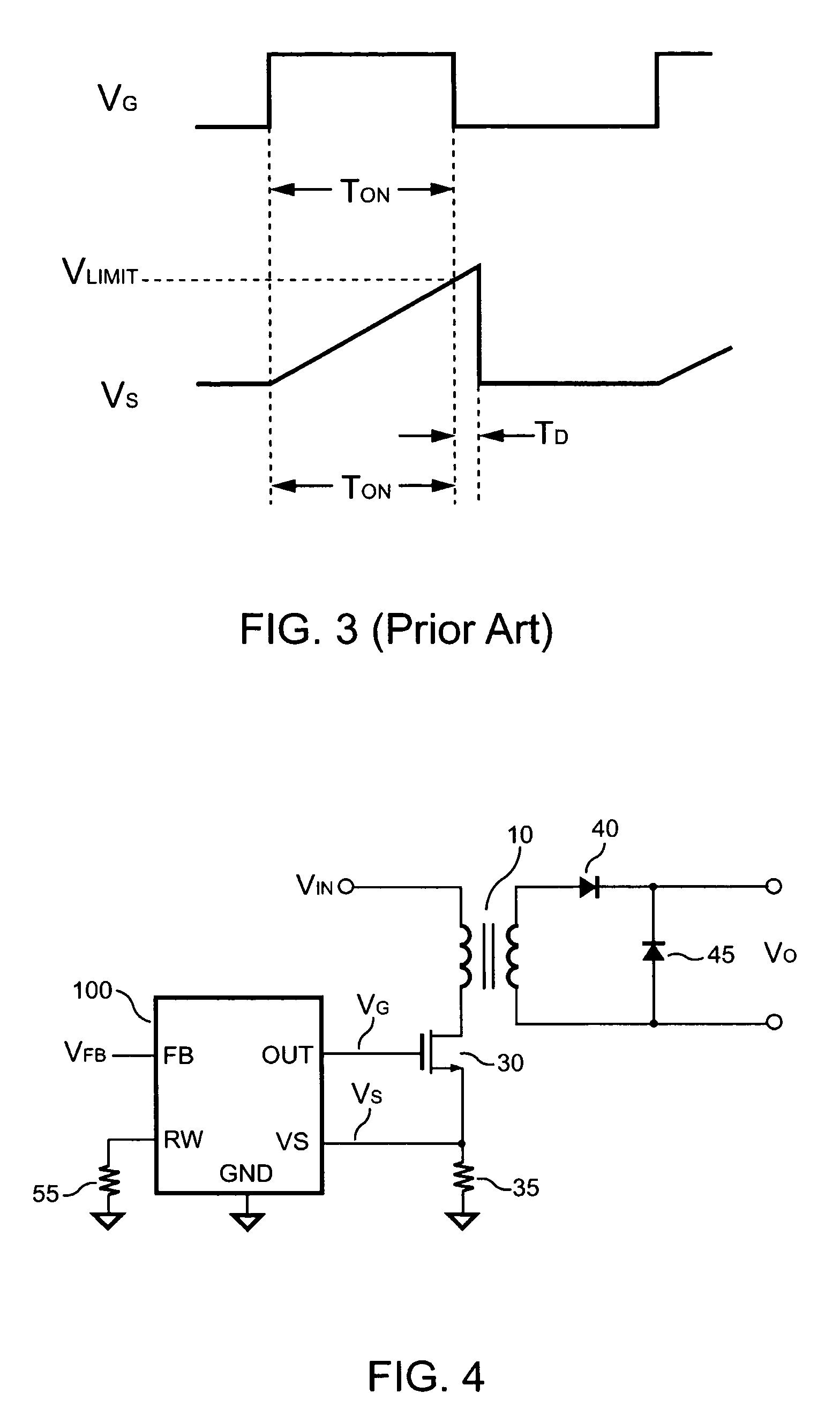
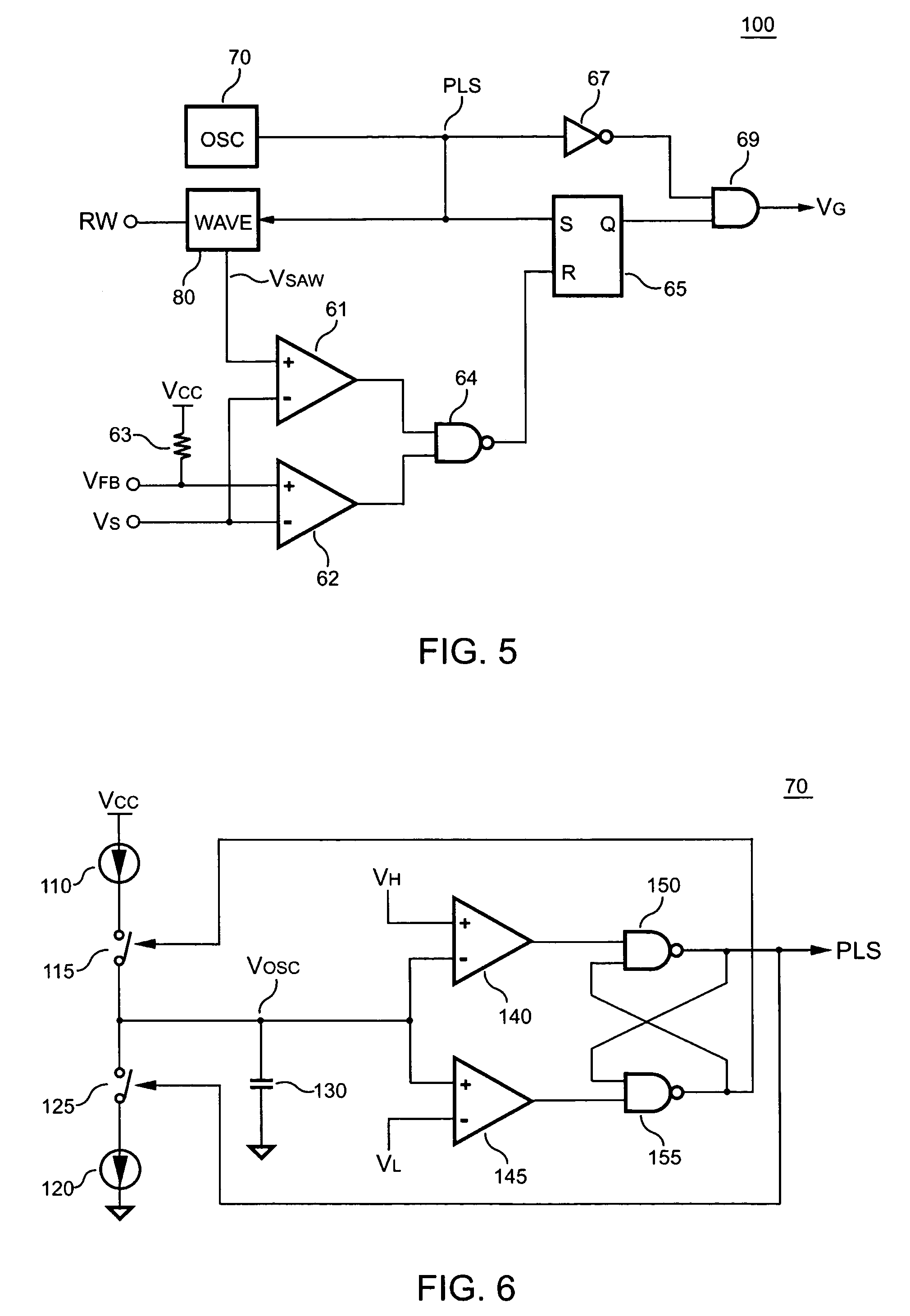
[0034]FIG. 4 shows a power converter having control circuit 100 in accordance with the present invention. The control circuit generates the control signal VG to control the switch 30. The switch 30 is coupled to the transformer 10 for switching the transformer 10 and transferring the energy to the output of the power converter. The resistor 35 is connected to the switch 30 for detecting and converting the switching current of the switch 30 to the current signal VS. The current signal VS is further coupled to the control circuit 100 for the output power control. A resistor 55 is connected to the control circuit 100 for programming a waveform signal VSAW for the output power limit of the power converter. FIG. 5 illustrates the circuit schematic of the control circuit 100 comprises an oscillation circuit 70, a first circuit, a second circuit 80 and a terminal RW for connecting the resistor 55. The oscillation circuit 70 generates an oscillation signal PLS. The first circuit includes a ...


PUM


Abstract

A control circuit having a programmable waveform for the output power limit comprises an oscillation circuit to generate an oscillation signal. The oscillation signal is used for producing a switching signal to control a switching device in response to a feedback signal of the power converter. A waveform generator generates a waveform signal in accordance with the oscillation signal. The waveform signal controls the control signal and limits the output power of the power converter. A resistor is coupled to the waveform generator to program the waveform of the waveform signal. By properly selecting the resistance of the resistor, which can be used to achieve an identical output power limit of the power converter for the low line and high line voltage input.

Description

BACKGROUND OF THE INVENTION[0001]1. Field of the Invention[0002]The present invention relates to a power converter, and more particularly, to a control circuit used for limiting the output power of a switching power converter.[0003]2. Description of Related Art[0004]The switching power control is a conventional technology used in a power converter to control and regulate the output power. Various protection functions, such as over-voltage and over-current protections, are built-in in the power converter to protect the power converter and circuits connected thereto from permanent damage. The function of output power limit is generally used for overload and short-circuit protection. Referring to FIG. 1, a traditional power converter circuit includes a feed-forward compensation. A control circuit 50 generates a control signal VG to regulate the output of the power converter in response to a feedback signal VFB. The control signal VG drives a switch 30 for switching a transformer 10. A ...

Claims


Application Information

Patent Timeline
Patent Type & Authority Patents(United States)
IPC IPC(8): H02J1/00H02M3/00H02M3/22
CPCH02M3/33507H02M1/32
Inventor YANG, TA-YUNG
Owner SEMICON COMPONENTS IND LLC
Why Eureka
Try Eureka