Linear brushless D.C. motor with stationary armature and field and with integratable magnetic suspension

a brushless d.c. motor and stationary armature technology, applied in the field of brushless motors, can solve the problems of not being able to extend the motion of the structure, requiring considerable magnetic material, not being low cost nor lightweight, etc., to improve heat rejection, shorten the flux path, and extend the operational capacity

Active Publication Date: 2009-11-17
SHAPERY SANDOR WAYNE
View PDF16 Cites 23 Cited by
  • Summary
  • Abstract
  • Description
  • Claims
  • Application Information

AI Technical Summary

Benefits of technology

[0025]It represents a chance for the US to overtake the German and Japanese many year lead by eliminating the formidable expense of powered railways and exotic superconductors.
[0026]One aspect of the invention is a motor that separates the functional elements of an electronically commuted linear direct current motor into three parts, yielding unique characteristics. The field assembly may consist of two distinct parts, one of which contains the source of magnetic flux and is fixed to the armature, the other free to move linearly with respect to the armature. The other part of the field assembly may receive flux across an airgap, divide it into multiple poles, the poles interdigitated with another of opposite polarity, both facing the armature. The motor may have a variable field enabling the motor characteristic to be varied dynamicall

Problems solved by technology

Actuators may be defined as short linear or rotary devices and have unique structures not feasible for extended motion.
They are efficient, have control linearity, but require considerable magnetic material, are not low cost nor lightweight.
They are readily implemented in linear form and minimize the magnetic design but few applications reach linear velocities which warrant their large magnet requirement to drive flux across an airgap wide enough to accommodate the armature windings.
The commutation of linear motors trailed far behind that of r

Method used


Image

  • Linear brushless D.C. motor with stationary armature and field and with integratable magnetic suspension
  • Linear brushless D.C. motor with stationary armature and field and with integratable magnetic suspension
  • Linear brushless D.C. motor with stationary armature and field and with integratable magnetic suspension

Examples


Embodiment Construction

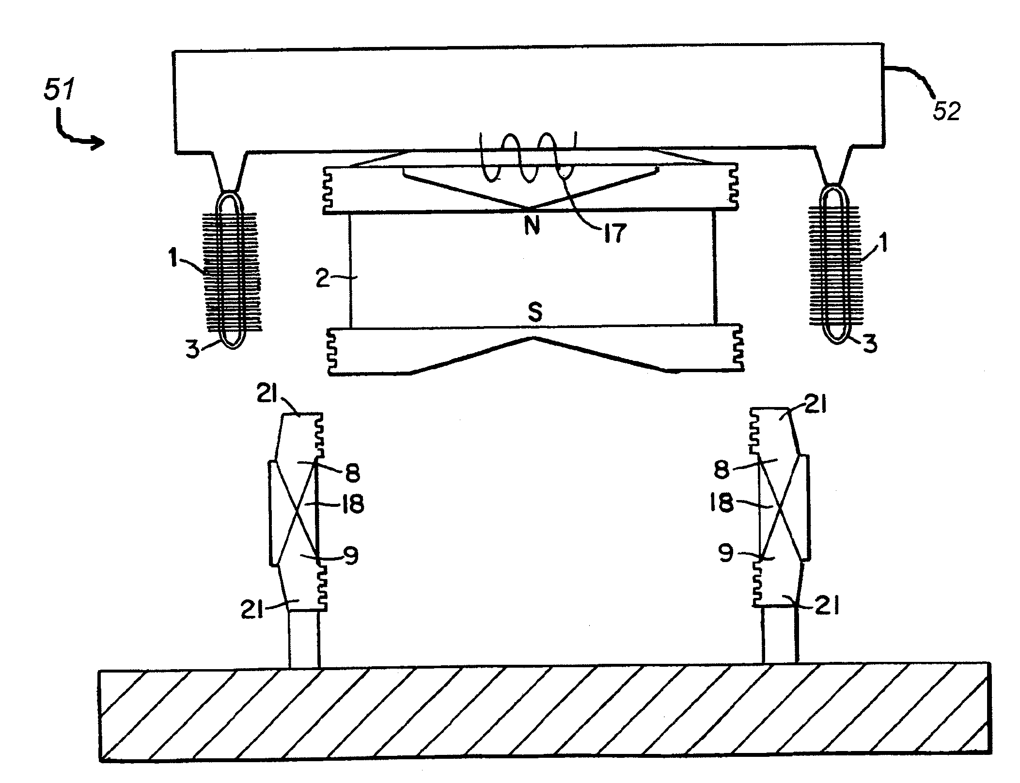
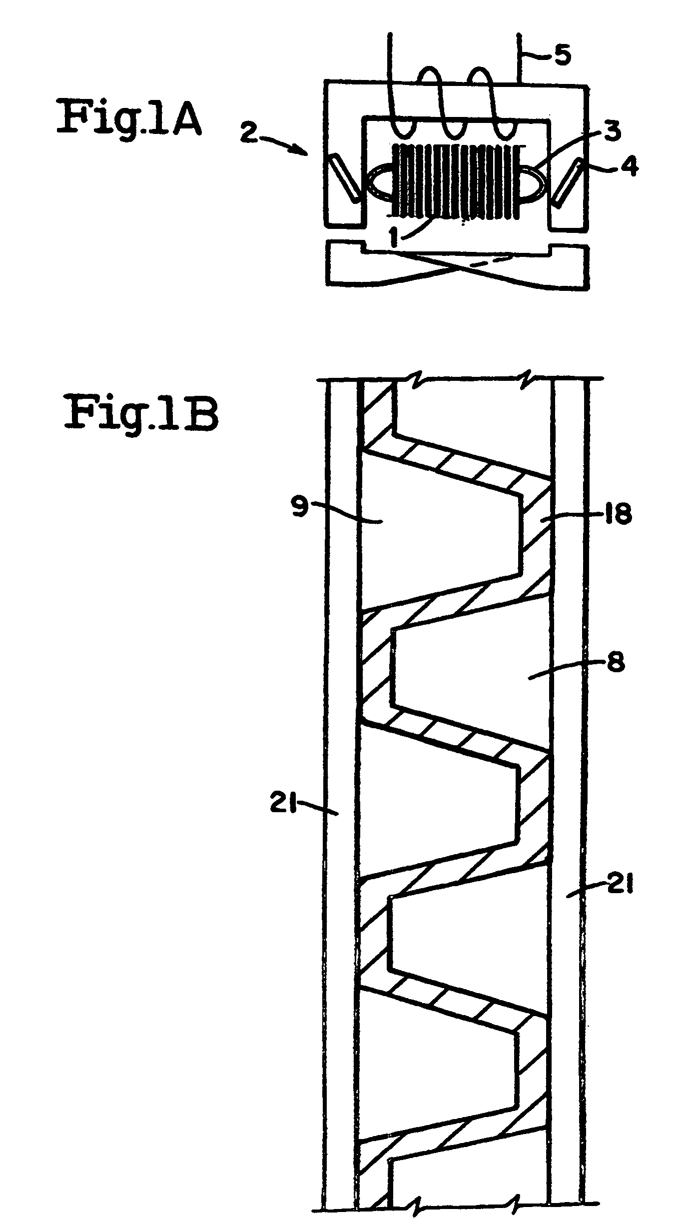
[0032]FIG. 1 illustrates a three element linear d.c. motor. Illustrated are the three parts of this novel motor. The armature 1 is standard, the field 2 is composed of a piece containing the source of magnetic flux 4 (stationary with respect to the armature), and the third element is a part with continuous axial surfaces 21 and interdigitated salient poles 8, 9, separated by a non-magnetic material 18.

[0033]An ironless armature version of the motor of FIG. 1 can also be employed, having the functionally same parts with the unique armature 1 containing no ferrous material formed in such a way to force magnetic flux thru a set of conductors (normally of three phases, connected for electronic commutation) in alternating directions to generate an e.m.f. when moved linearly with respect to each other, and axial thrust when energized by a suitable current source.

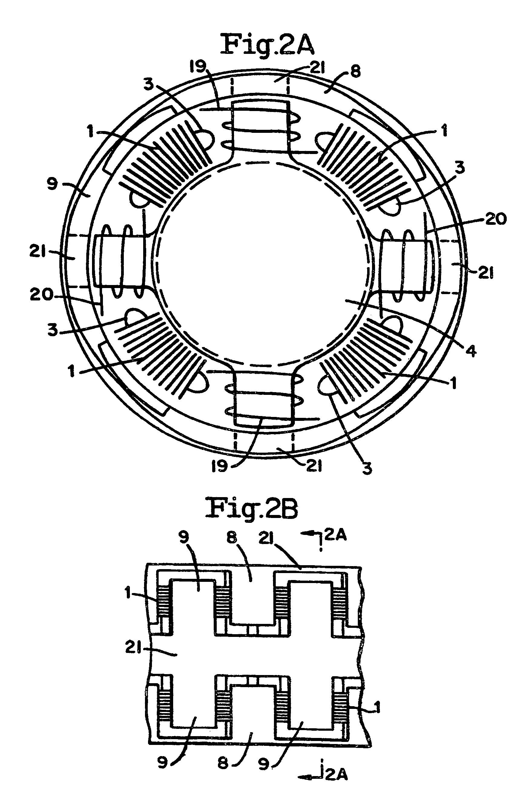
[0034]FIG. 2 illustrates a cylindrical form of a linear brushless d.c. motor with stationary armature and field. FIG. 2a shows a...


PUM


Abstract

This disclosure describes an electromagnetic system for efficient propulsion, suspension, and guidance. The track is inexpensive totally passive steel. This linear form of the D.C. motor provides traction motor characteristics without physical contact, The moveable element (vehicle) comprises both the integrated armature and field magnet flux source which induces magnetizing flux into pairs of rails each energizing a set of interdigitated poles of alternating polarity in the track against which its own armature conductors interact for thrust and braking. This source of magnetic flux requires no power and provides passive suspension at any speed and, with control, guidance. The permanent magnet and control flux in common airgaps multiply the effectiveness of lateral control for magnetic stabilization and to restrain external forces.

Description

CROSS-REFERENCE TO RELATED APPLICATIONS[0001]This application claims priority to U.S. Provisional Application No. 60 / 627,706, filed on Nov. 15, 2004.BACKGROUND OF THE INVENTION[0002]1. Field of the Invention[0003]This invention relates to brushless motors, and in particular to linear brushless motors.[0004]2. Description of the Related Art[0005]The history of linear motor technology dates far into the past. To simplify, this will be divided into the electromagnetic design and the commutation. With regard to the electromagnetics, motor technology proceeded primarily in rotary form. The linear motor form is also old, this can further broken into actuators and linear motors. Actuators may be defined as short linear or rotary devices and have unique structures not feasible for extended motion. Linear motors are defined here as electromagnetic devices which need or use commutation to extend their range of useful stroke.[0006]The electromagnetic design of linear motors follows the well-kn...

Claims


Application Information

Patent Timeline
IPC IPC(8): B60L13/00H02K41/00
CPCH02K41/03H02K7/09
Inventor STUDER, PHILIP ALBERT
Owner SHAPERY SANDOR WAYNE
Why Eureka
Try Eureka