Special cooling coating design for fossil fuel, nuclear, geothermal, and solar heat driven power plants; for HVAC cooling applications; and for heat rejection systems

a technology of fossil fuels and heat-driven power plants, which is applied in the direction of mechanical equipment, indirect heat exchangers, lighting and heating apparatus, etc., can solve the problems of clogging fresh water intakes, adverse environmental impacts of traditional power plant cooling methods, and vaporizing salt water from seawater-cooled power plants, etc., to improve cooling equipment efficiencies, reduce condensing and/or cooling equipment and/or energy requirements, and positive effect on the environmen

Active Publication Date: 2020-05-19
DEEP WELL POWER
View PDF9 Cites 0 Cited by
  • Summary
  • Abstract
  • Description
  • Claims
  • Application Information

AI Technical Summary

Benefits of technology

[0012]In view of the foregoing, it would be advantageous to provide cooling means that at least one of decreases condensing and / or cooling equipment and / or energy requirements, and increases cooling equipment efficiencies, as well as having a positive impact on the environment.
[0013]The ability to provide at least one of an actual economic, an efficiency, and an environmentally friendly cooling advantage would be afforded by coating the exterior of heat exchange tubing (such as metal tubing, plastic tubing, finned tubing, micro-channels, or the like) used to transport a working fluid, thereby enhancing the exchange of heat from the working fluid inside the heat exchange tubing to the ambient environment surrounding the heat exchange tubing. The coating may be a silicon carbide and silicon dioxide coating, or the like, designed to release heat radiation in wavelengths of between about 7.9 and 13.0 micrometers. This coating enhances rejection of heat into surrounding space with minimal interference from air molecules in the earth's atmosphere, thereby increasing the overall cooling efficiency of at least one of a power production system, an HVAC cooling system, and most any other cooling system utilizing heat rejection to air.
[0014]The coating disclosed herein significantly enhances heat transfer from a cooling system's primary working fluid as unwanted heat travels through piping / tubing, or the like, containment walls, through the special coating, and then to the exterior air and / or space, and will thereby increase cooling system operational efficiencies, while simultaneously reducing potential adverse environmental impacts otherwise caused by increased cooling work.

Problems solved by technology

Traditional power plant cooling methods can have adverse environmental impacts.
For example, using river and / or lake water to condense and / or sub-cool the closed-loop water working fluid in large power plants in the summer can result in the river and / or lake water becoming so warm that it kills native fish and / or other aquatic life, or in becoming so warm so that it enhances the quantity of zebra muscles, which can clog up fresh water intakes, or the like.
Also, as another example, vaporized salt water from seawater-cooled power plants can impair vegetation and / or farmland for miles around such a power production facility.
Further, as natural river and / or lake water naturally heats up in the summer, power plant operational temperature differentials deteriorate and power production abilities decrease.
Instead of using an exterior water source to cool closed-loop water working fluid in a power plant, as an example, condensing and / or cooling the primary closed-loop water working fluid with air can be expensive, requiring large arrays of finned tubing, or the like, often with parasitic power-consuming fans so as to increase airflow and the cooling effect.
Also, as outdoor air temperatures rise during the summer (just as with rising natural water temperatures when water is used for cooling), decreases in the primary working fluid temperature differentials result, and cooling abilities correspondingly disadvantageously decrease.
This, in turn, results in more cooling equipment and / or more fan power being required, and / or in lower than optimum design power output.
When design levels of working fluid cooling cannot be attained, normal operational design levels of power production in power plants, and normal operational design levels of cooling abilities in HVAC systems, typically cannot be supplied.

Method used


Image

  • Special cooling coating design for fossil fuel, nuclear, geothermal, and solar heat driven power plants; for HVAC cooling applications; and for heat rejection systems
  • Special cooling coating design for fossil fuel, nuclear, geothermal, and solar heat driven power plants; for HVAC cooling applications; and for heat rejection systems

Examples


Embodiment Construction

[0030]The following detailed description is of the best presently contemplated mode of carrying out the subject matter disclosed herein. The description is not intended in a limiting sense, and is made solely for the purpose of illustrating the general principles of this subject matter. The various features and advantages of the present disclosure, none of which are drawn to scale, may be more readily understood with reference to the following detailed description taken in conjunction with the accompanying drawings.

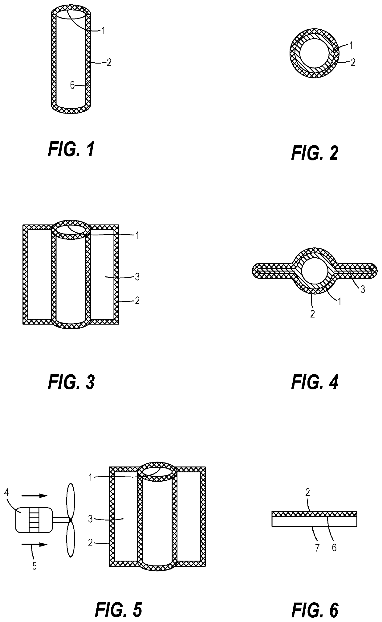
[0031]Referring now to the drawings in detail, where like numerals refer to like parts or elements, there is shown in FIG. 1 a side view, not drawn to any scale, of a working fluid containment tube 1 surrounded by and / or coated with the special coating 2 described herein. The special coating 2 is comprised of a silicon carbide and silicon dioxide coating, or the like, designed to release heat radiation in wavelengths of between about 7.9 and 13.0 micrometers. The special ...


PUM

PropertyMeasurementUnit
wavelengthsaaaaaaaaaa
pressuresaaaaaaaaaa
pressuresaaaaaaaaaa

Abstract

At least one of a heat-driven power generation system, an HVAC system, a system requiring heat rejection from its working fluid, and any object where cooling is advantageous where the portion of at least one of the exterior working fluid containment tubing and the exterior surface area exposed to air that is used for heat rejection is coated with a special coating designed to enhance heat rejection to the exterior air and / or space with minimal interference from air molecules in the earth's atmosphere.

Description

FIELD OF THE DISCLOSURE[0001]The present disclosure relates to methods and apparatus for cooling and / or condensing fluids in fossil fuel, nuclear, geothermal, and solar heat-driven power plants, and / or in heating, ventilating, and air conditioning (HVAC) cooling applications, and / or in heat rejection systems.BACKGROUND OF THE DISCLOSURE[0002]Most traditional fossil fuel, nuclear, and solar heat-driven power plants typically utilize water (R-718) as a primary phase change working fluid for cooling purposes. In HVAC applications, a refrigerant, such as R-410A, R134A, R744 CO2, or the like, is typically utilized as a phase change working fluid for cooling purposes. Typically, at least one of water and a refrigerant is utilized as the working fluid in other types of heat rejection systems operating with a working fluid, although simple heat rejection may sometimes be accomplished through a flat plate, or the like.[0003]Water is readily available and inexpensive, and has therefore been t...

Claims


Application Information

Patent Timeline
Patent Type & Authority Patents(United States)
IPC IPC(8): F28F13/18C09D5/26F28D21/00F16L9/14F28F21/04B05D5/00
CPCC09D5/26B05D5/00F16L9/14F28D21/00F28F13/182F28F21/04F28D2021/0059F28D2021/0068F28D2021/0061C08K3/14C08K3/36C09D5/00C09D7/61F28F13/18
Inventor WIGGS, B. RYLAND
Owner DEEP WELL POWER
Why Eureka
Try Eureka