Thin film solar cell thermal radiator

a solar cell and thermal radiator technology, applied in the field of thin film solar cells and heat radiators, can solve the problems of obstructing thermal transmission through the solar cell, obstructing the integration of solar power modules, and limited amount of additional thermal energy that can be rejected from thin film solar cells that have mounted active heat producing components, etc., to achieve efficient radiation of waste heat and waste heat

Active Publication Date: 2007-08-21
THE AEROSPACE CORPORATION
View PDF3 Cites 0 Cited by
  • Summary
  • Abstract
  • Description
  • Claims
  • Application Information

AI Technical Summary

Benefits of technology

[0007]The present invention is directed to a thin film structure that efficiently radiates waste heat, particularly useful in thin film solar cells. In the thin film solar cell, the heat producing electronic components are located behind the solar cell top contact that functions as a thermal radiator. Waste heat generated from bottom mounted electronic components is routed in a first vertical direction, a second horizontal direction, and a third vertical direction, prior to thermal radiation rejection of the waste heat. The invention radiates waste heat using a horizontal metallic bus bar within the multilayer thin film structure, while preserving top silver contacts and the top coverglass layer. The horizontal metallic bus bar that routes power as well as effectively routing waste heat horizontally, from behind the top silver contacts to the sides of the top silver contacts, so that waste heat generated under the top silver contacts where the waste heat can be routed and be ejected through the top coverglass layer.
[0008]The coverglass is transparent in the visible and near infrared spectrum and has high thermal emissivity. The silver contact reflects radiation in the visible and near infrared spectrum. The emissivity and reflectivity of the coverglass and silver contact minimize absorption of unwanted solar energy while maximizing the emission of heat in the long infrared spectrum. Consequently, the temperature under the silver contact is minimized, such that, waste heat spread under the silver contact is more effectively radiated. A thermal emissive configuration uses a horizontally disposed power bus in a thermal conducting layer. The power bus overlaps mounted electronic devices so as to collect heat from these heat generating electronic devices and then routes heat to the side of the top silver contacts. The power bus serves to vertically collect and then horizontally spread the waste heat for improved heat rejection from the top coverglass layer around the sides of the top silver contacts. In this configuration, existing solar cell technologies can be made with thin film circuit boards and mounted electronic components generating waste heat, which is efficiently ejected from the thin film solar cell. These and other advantages will become more apparent from the following detailed description of the preferred embodiment.

Problems solved by technology

However, the integrated solar power module does not address the problem of rejecting excessive heat produced by the active electronic components that are mounted on the back of the thin film solar cell substrate.
The bus bars and solar cell structure obstruct thermal transmission through the solar cell.
The amount of additional thermal energy that can be rejected from a thin film solar cell that has mounted active heat producing components is limited.

Method used


Image

  • Thin film solar cell thermal radiator
  • Thin film solar cell thermal radiator
  • Thin film solar cell thermal radiator

Examples


Embodiment Construction

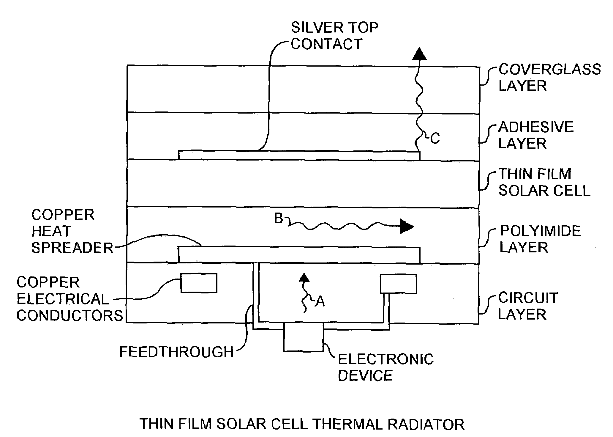
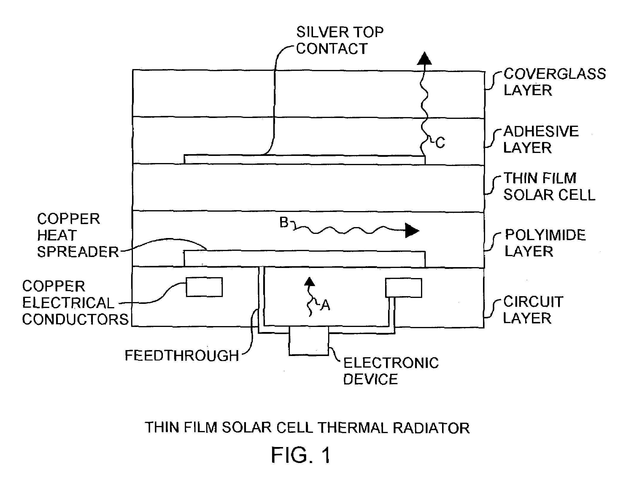
[0011]An embodiment of the invention is described with reference to the figures using reference designations as shown in the figures. Referring to FIG. 1, a thin film solar cell thermal radiator configuration a silver top contact is shown presenting a conventional thin film solar cell. The silver top contact is reflective and functions as a thermal barrier. An adhesive layer is used to secure a coverglass layer over the thin film solar cell. A copper heat spreader is disposed in a polyimide layer. A circuit layer on the polyimide layer has necessary conductors for routing power and signals through feedthroughs to an electronic device generating waste heat. The circuit layer and polyimide layer function as a flexible printed circuit for supporting the thin film solar cell. The flexible printed circuit would be mounted on the back of the thin film solar cell over the copper heat spreader. The copper heat spreader is deposited on the back of the polyimide layer that functions as a depo...


PUM


Abstract

A thin film solar cell thermal radiator configuration uses an embedded power bus to collect vertically migrating waste heat from electronic devices mounted on a thin film multilayer printed circuit board. The waste heat is vertically collected, horizontally spread, and vertically rejected through the a top coverglass glass layer around the side of a top silver contact of conventional thin film solar cells. The thermal radiator configuration enables the collection and rejection of the electronic component waste heat for maintaining thin film solar cells within desired temperature ranges.

Description

FIELD OF THE INVENTION[0001]The invention relates to the field of thin film solar cell and heat radiators. More particularly, the present invention relates to thin film power bus bars for radiating heat in solar cells.BACKGROUND OF THE INVENTION[0002]The aerospace industry has developed designs for microsatellites and nanosatellites. This development of small space systems is likely to increase with new technologies that can be used to incorporate multiple functions in a small satellite. In U.S. Pat. No. 6,300,158 titled Integrated Solar Power Module, a method is described for producing thin film solar cells that are integrated with a multilayer printed wiring board and power processing electronics. However, the integrated solar power module does not address the problem of rejecting excessive heat produced by the active electronic components that are mounted on the back of the thin film solar cell substrate.[0003]Active electronic components convert some of the electrical energy pas...

Claims


Application Information

Patent Timeline
Patent Type & Authority Patents(United States)
IPC IPC(8): H01L31/052H01L25/00H01L31/00H01L31/048
CPCH01L31/048H01L31/052Y02E10/52Y10S136/293Y02E10/50
Inventor SIMBURGER, EDWARD J.GILMORE, DAVID G.
Owner THE AEROSPACE CORPORATION
Why Eureka
Try Eureka