
Refueling vapor recovery system

a vapor recovery and refueling technology, applied in the field of vehicle fuel systems, can solve the problems of degrading the vapor recovery system, liquid fuel entering the recirculation tube, and increasing government regulations placed on the automotive industry, so as to reduce the size and manufacturing cost of the canister, prolong the life of the canister, and reduce the vapor release to the atmosphere

Active Publication Date: 2009-11-17
TI GRP AUTOMOTIVE SYST LLC
View PDF30 Cites 22 Cited by
  • Summary
  • Abstract
  • Description
  • Claims
  • Application Information

AI Technical Summary

Benefits of technology

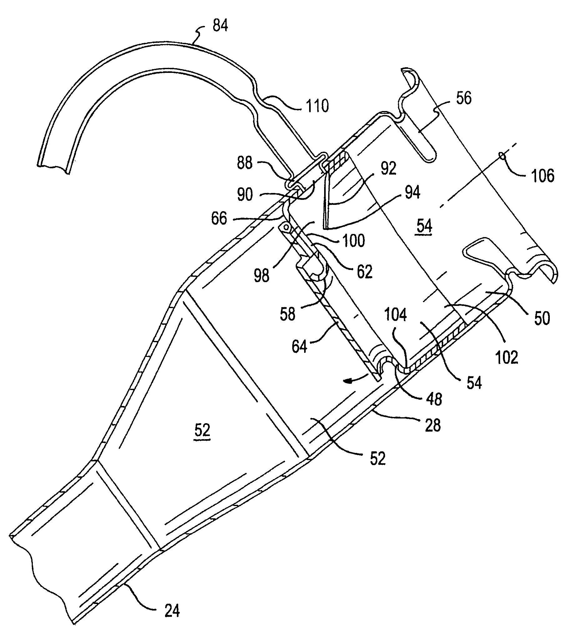
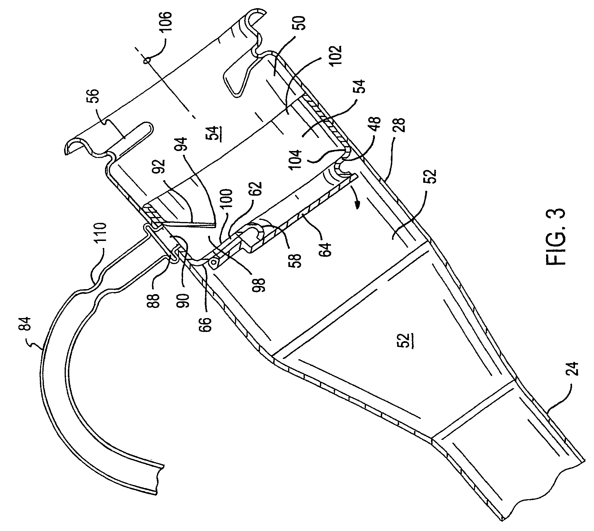
[0006]A fuel vapor recovery system of a vehicle has a fill pipe inlet assembly located at a distal end of a fuel tank fill pipe. The inlet assembly has a cylindrical wall defining an elongated cavity divided axially into upstream and downstream regions by a restrictor plate which carries a hole for close receipt of a fuel supply nozzle of a remote fuel pump. During refueling of the tank, fuel vapor flows from the tank via a recirculation tube and into the inlet cavity of the fill pipe to become entrained into the flowing liquid fuel as opposed to being released to atmosphere. The fuel vapor enters the upstream region at an aperture carried by the wall disposed immediately upstream from the restrictor plate and downstream from a hood. The hood limits vapor release to atmosphere and draws the vapor downstream through a port carried by the restrictor plate for entrainment of vapor into the liquid fuel in the downstream region. Toward the end of the refueling process, any fuel welling or backing up within the fill pipe is generally limited to the downstream region of the cavity via the restrictor plate and an automatic shutoff feature of the remote fuel pump. Liquid fuel is thus less likely to enter the recirculation tube in the upstream region even if the automatic shut-off feature of the remote refueling pump should fail. Consequently, it is less likely that liquid fuel will flow into the canister of the vapor recovery system even when the automatic shut-off feature of the remote refueling pump has failed.
[0007]Objects feature and advantages of this invention include providing a vapor recovery system that is resistant to carbon canister flooding, prolongs canister life, permits reduced canister size and manufacturing cost, reduces vapor release to atmosphere, is a relatively simple, robust and inexpensive design with no maintenance and an overall prolonged useful life.

Problems solved by technology

On-going environmental concerns have resulted in increasingly stringent government regulations placed upon the automotive industry.
Unfortunately, because the outlet aperture is located below the restrictor plate it is dependent upon the automatic shutoff feature of the remote fuel supply pump to prevent liquid fuel from entering the recirculation tube through the aperture.
If the shutoff feature of the nozzle or remote fuel pump is not sufficiently responsive, or should the feature fail altogether, fuel backing up into the fill pipe can cause liquid fuel to enter the recirculation tube.
The reverse flow of liquid fuel through the recirculation tube from the outlet aperture can degrade the vapor recovery system by potentially flooding the carbon canister and destroying the carbon bed.

Method used


Image

  • Refueling vapor recovery system
  • Refueling vapor recovery system
  • Refueling vapor recovery system

Examples


Embodiment Construction

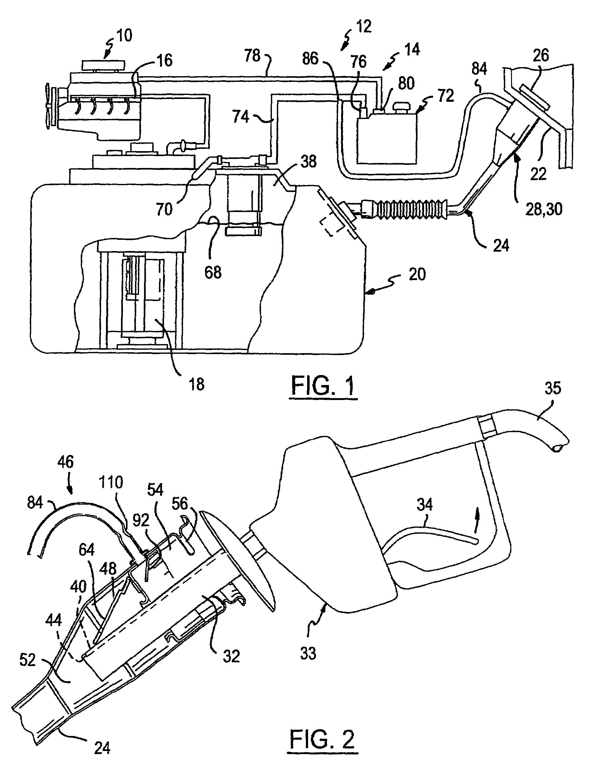
[0013]Referring in more detail to the drawings, FIG. 1 illustrates a combustion engine 10 of a vehicle serviced by a fuel system 12 having a vapor recovery system 14 of the present invention. Conventionally, a fuel rail 16 of the engine 10 receives pressurized liquid fuel from a fuel pump 18 submerged in liquid fuel contained by an on-board fuel tank 20. A downward sloped fuel fill pipe 24, through which liquid fuel is added to the tank 20, connects between an exterior body panel 22 of the vehicle and the fuel tank 20.

[0014]When refueling the tank 20, the engine 10 is preferably shut down and a sealable and removable gas cap 26 is removed from the open end 30 of the fill pipe 24 received adjacent to the body panel 22. As best illustrated in FIG. 2, during refueling, a refueling pump nozzle 32 projecting from a trigger handle 33 and connected to a remote fuel pump (not illustrated) of a refueling station via a supply hose 35, is inserted into the distal end 30 of the fill pipe 24 and...


PUM

PropertyMeasurementUnit
volatileaaaaaaaaaa
sizeaaaaaaaaaa
weightaaaaaaaaaa

Abstract

A fuel vapor recovery system of a vehicle has a fill pipe inlet assembly located at a distal end of a fuel tank fill pipe. The inlet assembly has a cylindrical wall defining an elongated cavity divided axially into upstream and downstream regions by a restrictor plate which carries a hole for close receipt of a fuel supply nozzle of a remote fuel pump. During refueling of the tank, fuel vapor flows from the tank via a recirculation tube and into the inlet cavity of the fill pipe to become entrained into the flowing liquid fuel as oppose to being released to atmosphere. The fuel vapor enters the upstream region at an aperture carried by the wall disposed immediately upstream from the restrictor plate and downstream from a hood. The hood limits vapor release to atmosphere and draws the vapor downstream through a port carried by the restrictor plate for entrainment of vapor into the liquid fuel in the downstream region. Toward the end of the refueling process, any fuel welling or backing up within the fill pipe is generally limited to the downstream region of the cavity via the restrictor plate and an automatic shutoff feature of the remote fuel pump. Liquid fuel is thus less likely to enter the recirculation tube in the upstream region even if the automatic shut-off feature of the remote refuel pump should fail. Consequently, it is less likely that liquid fuel will flow into the canister of the vapor recovery system even when the automatic shut-off feature of the remote refuel pump has failed.

Description

FIELD OF THE INVENTION[0001]The present invention relates to a vehicle fuel system and more particularly to a refueling vapor recovery system.BACKGROUND OF THE INVENTION[0002]On-going environmental concerns have resulted in increasingly stringent government regulations placed upon the automotive industry. One area of concern is the release of volatile hydrocarbon fuel vapors during refueling of a vehicle. A conventional vapor recovery system is described in U.S. Pat. No. 5,960,817, filed Nov. 3, 1997, and is incorporated herein by reference. When filling a fuel tank with volatile hydrocarbon fuel (or even diesel fuel), the air and fuel vapor in the tank is in-part filtered and displaced to atmosphere. Fuel vapor is removed from the displaced air before release to atmosphere by a fuel vapor storage canister that contains activated charcoal for absorbing the hydrocarbon vapors flowing from the fuel tank and later generally releasing the vapors to an intake manifold of an operating eng...

Claims


Application Information

Patent Timeline
Patent Type & Authority Patents(United States)
IPC IPC(8): B65B3/04B60K15/035B67D7/06B60K15/04B60K15/077B67D99/00
CPCB60K15/03504B60K15/04B60K2015/03557B60K2015/03523Y10T137/86332Y10T137/87539B67D7/06B67D99/00
Inventor BARNES, TIMOTHY J.BOOMS, WALLACE J.HILDERLEY, STEVEN R.YAGER, JEFFREY L.
Owner TI GRP AUTOMOTIVE SYST LLC
Learn More