Endoscopic rotary abrader

a rotary abrader and endoscope technology, applied in trocar, medical science, surgery, etc., can solve the problems of limiting the surgeon's access to some structures, obscuring the surgeon's view of the site being abraded, and undesirable contact between the burr head and the hood, so as to achieve the effect of increasing the displacement between the center of the outer tube and the center of the inner assembly, increasing the clearance, and reducing the siz

Active Publication Date: 2009-11-17
ARTHREX
View PDF11 Cites 17 Cited by
  • Summary
  • Abstract
  • Description
  • Claims
  • Application Information

AI Technical Summary

Benefits of technology

[0024]The resistance of the burr head to lateral deflection is enhanced by the placement of the bearing in close proximity to the burr head. The burr head is shifted away from the hood by the offset in the bearing. This combination of enhanced rigidity and eccentricity of the inner assembly and outer tube allows the diameter of the outer tube to be decreased, or the diameter of the abrading element to be increased, thereby minimizing obstruction of the surgeon's view and improving access to structures within a joint.
[0027]The unique construction of this second embodiment provides advantages for certain applications. In the first embodiment, the diameter of the cylindrical portion of the inner assembly is greater than the diameter of the tubular portion, so as to allow the inner assembly to be inserted proximally into the bearing of the outer assembly. The tubular portion must be of sufficient diameter to transmit required torque to the abrading element, and have a lumen of sufficient size for effective aspiration. The minimum diameter for the tube determines the minimum diameter of the cylindrical element, which, in turn, determines the bearing configuration and the distance that the burr head can be shifted laterally away from the hood.
[0028]In the second embodiment, the cylindrical portion of the inner assembly can be smaller than the tubular portion since the inner assembly is not inserted into the bearing axially but rather is positioned between two halves of a split bearing. This allows the displacement between the center of the outer tube and the center of the inner assembly to be increased, allowing further increase in the clearance between the burr head and the hood for a given tube size. This, in turn, gives improved visibility for the surgeon and enhanced access to structures within a joint. Another advantage of the second embodiment is the ease of disassembly and reassembly for cleaning. This is essential for a reusable instrument.

Problems solved by technology

Contact between the burr head and the hood is undesirable since the burr will abrade metal from the hood and deposit metallic debris in the joint.
While this increased diameter prevents contact between the burr head and the hood, it also restricts the surgeon's access to some structures, and often obscures the surgeon's view of the site being abraded.
Insufficient flow causes decreased visibility because of residual debris suspended in the intra-articular fluid.
This, in turn, necessitates larger clearance between the burr head and the hood, and thus a large hood diameter, which obscures the surgeon's view and access.
The relatively small slots in this design would make the instrument prone to clogging.
The design is likely quite effective when the instrument is fully inserted into the joint, however, there will likely be instances in which the openings are obstructed because the burr is not fully inserted into a joint, or the joint is small.
In these cases, it will be impossible to aspirate tissue through the instrument.
A potential problem with this method is that the burr is rotating at high speed and the centrifugal force would tend to move material away from the openings.
Also, it is likely that cavitation would tend to disrupt the flow of material into the openings, and proximally from the openings to the lumen in the inner tube.
It is likely that this passage would be prone to clogging unless it was made quite large, in which case the instrument diameter would be very large compared to that of the rotating abrading element.
This, in turn, requires the use of large cannulae and generally obstructs the surgeon's view.
This allows the bearing to be placed quite close to the burr head as to minimize deflection, however, the decreased bearing surface will likely lead to higher forces between the bearing and the rotating member making galling and the generation of metallic debris more likely.
Also, because of size constraints of the outer tube, the passages would be quite small and prone to clogging.
Clearing clogs would be problematic since access to the passages is limited by the burr head, and the burr could not be readily disassembled for clearing as the burr head is larger in size than the bearing surfaces thereby preventing the inner portion from being withdrawn proximally.
A drawback of this construction, however, as in the case of the Vaca et al. device, is that the slots may be obstructed by tissue when the instrument is initially inserted into the joint, or when it is used on a small joint.
Clogging, however, generally occurs at the distal end of the instrument, at the opening of the passage proximal to the burr head.
The clogging most frequently occurs because soft tissue wraps around the inner member proximal to the burr.

Method used


Image

  • Endoscopic rotary abrader
  • Endoscopic rotary abrader
  • Endoscopic rotary abrader

Examples


first embodiment

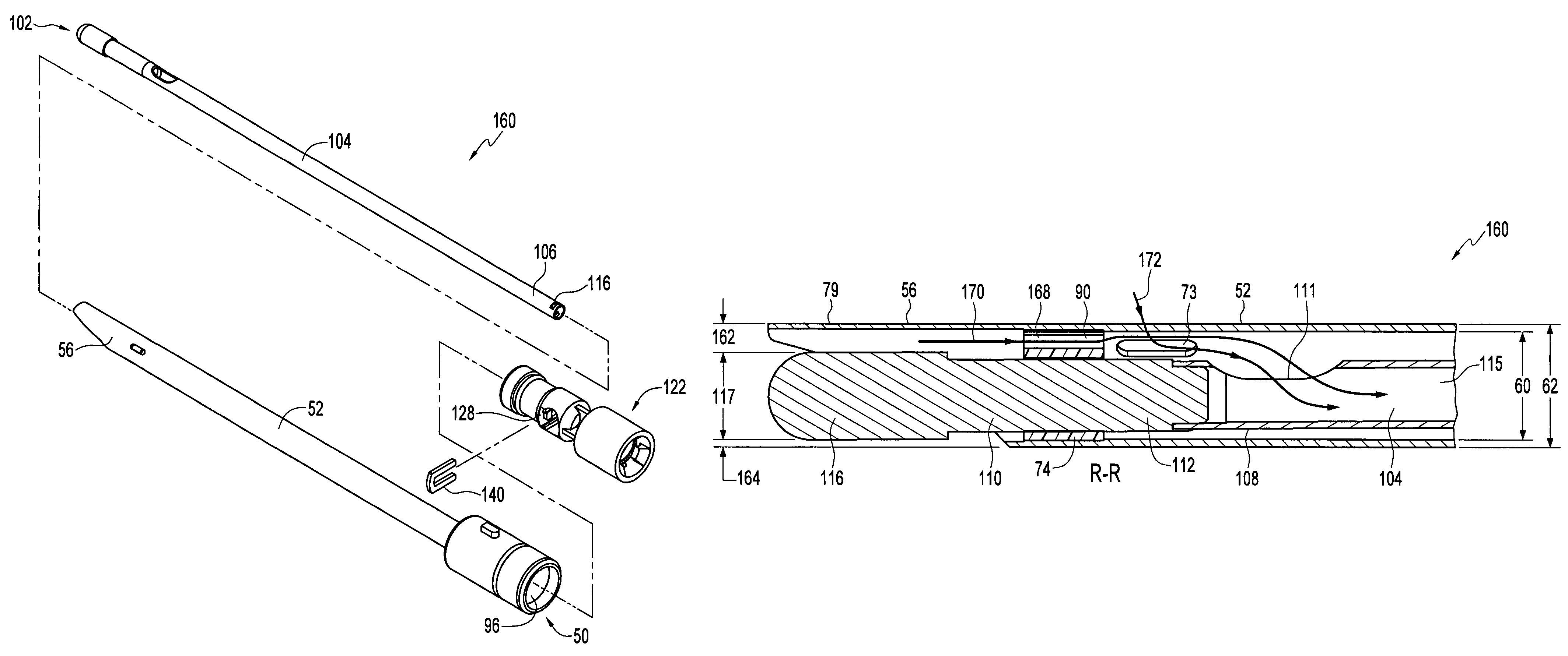
[0103]In the present invention, an inner assembly is rotatably positioned within an outer assembly. The proximal ends of the assemblies form hubs as in the prior art device of FIGS. 1 through 4. The elongated tubular portions of the inner and outer assemblies are not concentric, but rather have the inner tubular portion laterally positioned away from the hood so that required clearance can be maintained between the burr head and the hood while increasing the diameter of the burr head, or decreasing the diameter of the outer tube.

[0104]Referring now to FIGS. 5 through 7, showing the outer tubular portion (outer tube) 52 of the outer assembly 50 (FIG. 10) of a rotary abrader formed in accordance with the first embodiment of the invention, outer tube 52 has a proximal end 54 and a distal end 56. Tube 52 has a lumen 53 of diameter 60 and an outer diameter 62. Distal end 56 has a first portion 64 with an inner diameter 66 formed therein, and a second portion 68 of length 70 with a diamet...

second embodiment

[0117]the present invention avoids this limitation. The distal bearing has a first portion mounted to a first, fixed portion of the outer tube assembly, and a second portion mounted to a second, demountable portion of the outer tube assembly. To assemble the rotary abrader, the demountable portion of the outer tube is removed, the inner assembly with hub permanently attached is positioned within the fixed portion of the outer tube assembly, and the demountable portion of the outer assembly is remounted to the outer assembly. This construction has two advantages: the instrument can be easily disassembled for cleaning between uses, and the tubular portion of the inner assembly can have a larger diameter than the bearing so as to allow better transmission of torque and better aspiration of debris from the site.

[0118]Referring now to FIG. 29 showing an embodiment of the disclosed invention having a two-piece outer tubular assembly, rotary abrader 200 has an inner assembly 350, an outer ...

third embodiment

[0128]In the present invention, the elongated tubular portions of the inner and outer assemblies are concentric, rather than offset, but the burr head is enlarged. The hood is positioned at an angle and enlarged so that the required clearance can be maintained between the enlarged burr head and the hood. As in the previous embodiments, the larger diameter burr is preferably configured so that its cutting edge is aligned with the outer surface of the outer tube to provide a “flush cut.”

[0129]Referring now to FIGS. 60 through 64, showing the outer tubular portion (outer tube) 552 of the outer assembly 550 of a rotary abrader formed in accordance with the third embodiment of the invention, outer tube 552 has a proximal end 554 and a distal end 556. Tube 552 has a lumen 553 of diameter 560 and an outer diameter 562. Distal end 56 has a first portion 564 of length 556 and a second portion 568 of length 570. Three elongated aspiration slots 573, at 120° apart, extend from the lumen 553 to...


PUM


Abstract

An endoscopic rotary abrader allowing for increased burr size while maintaining the required minimum clearance between the burr and the hood. This is accomplished either by an offset configuration of non-concentric inner and outer tubes, where the inner tube is shifted laterally away from the hood, or by employing an enlarged hood.

Description

[0001]This application claims priority to U.S. Provisional Application No. 60 / 657,418 filed Mar. 2, 2005, the disclosure of which is incorporated herein in its entirety.FIELD OF THE INVENTION[0002]This invention relates to rotary abraders used in surgery and, more particularly, to an abrader which gives the surgeon an improved view of the surgical site during endoscopic surgery.BACKGROUND OF THE INVENTION[0003]Least invasive surgical techniques have gained significant popularity because of their ability to accomplish outcomes with reduced patient pain and accelerated return of the patient to normal activities. Arthroscopic surgery, in which the intra-aticular space is filled with fluid, allows orthopedists to efficiently perform procedures using special purpose instruments designed specifically for arthroscopists. Among these special purpose tools are various manual graspers and biters, electrosurgical devices, and powered shaver blades and rotary abraders. Shaver blades having holl...

Claims


Application Information

Patent Timeline
Patent Type & Authority Patents(United States)
IPC IPC(8): A61B17/22
CPCA61B17/32002A61B17/320758A61B17/320783A61B2017/320775A61B2017/320032
Inventor O'QUINN, PHILIP S.HACKER, RANDALL L.BICKENBACH, CHRISTINEGOLDSMITH, GERALDVAN WYK, ROBERT A.HEISLER, GARY R.
Owner ARTHREX
Why Eureka
Try Eureka