Grounding device and method of constructing the same

a grounding device and a construction method technology, applied in the direction of coupling device connections, electrical apparatus casings/cabinets/drawers, insulated conductors, etc., can solve the problems of needing more time and effort for construction of grounding devices, grounding devices composed of grounding bars driven into the earth may not offer a predetermined grounding resistance, and need for large time and effort for grounding devices. , to achieve the effect of small grounding resistance, small grounding resistan

Inactive Publication Date: 2009-11-17
SANKOSHA CORP
View PDF14 Cites 7 Cited by
  • Summary
  • Abstract
  • Description
  • Claims
  • Application Information

AI Technical Summary

Benefits of technology

[0011]The grounding device is configured so that the grounding member having the grounding conductor and the conductive laminated portion covering the grounding conductor is integrated with the foundation member of the building so that the grounding member and the foundation member overlap partly or entirely. This makes it possible to easily offer a small grounding resistance. Further, the foundation member of the building contacts the earth over a large area. This enables a small grounding resistance to be stably offered for a long period.
[0012]The grounding device is configured so that the grounding member having the grounding conductor and the conductive laminated portion covering the grounding conductor is integrated with the foundation member of the building are so that the grounding member and the foundation member overlap partly or entirely. This makes it possible to prevent the grounding conductor from corroding owing to the moisture in the earth. The grounding member and thus the grounding device can therefore last longer.
[0013]The method of installing a conducting device comprises installing the grounding member having the grounding conductor and the conductive laminated portion covering the grounding conductor, and then placing green concrete on the grounding member. Thus, compared to the conventional method of constructing a grounding device after constructing a building, the present method can save the time and effort required to check the earth for buried objects or the like. This makes it possible to sharply reduce the time and effort required to install the grounding device.

Problems solved by technology

This disadvantageously results in the need for much time and effort for construction of the grounding device.
The grounding device composed of the grounding bar driven into the earth may fail to offer a predetermined grounding resistance owing to the large specific resistance of the earth.
This disadvantageously results in the need for more time and effort for construction of the grounding device.
The grounding bar driven directly into the earth may corrode earlier owing to the moisture in the earth or the like.
This may disadvantageously prevent the grounding device from providing its original functions.

Method used


Image

  • Grounding device and method of constructing the same
  • Grounding device and method of constructing the same
  • Grounding device and method of constructing the same

Examples


Embodiment Construction

[0018]An embodiment of the present invention will be described below. However, the present invention is not limited to the present embodiment without departing from the spirit of the present invention.

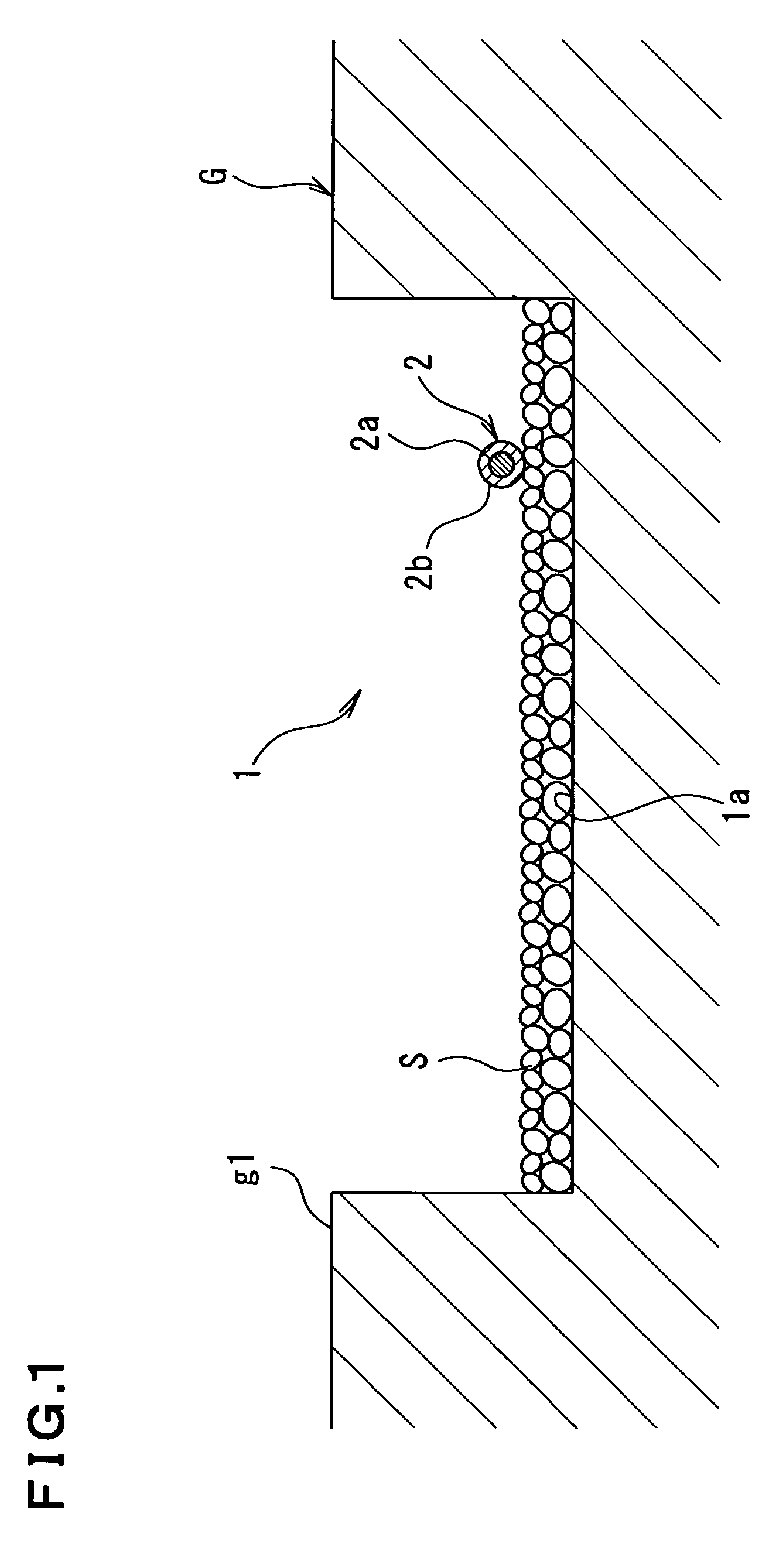
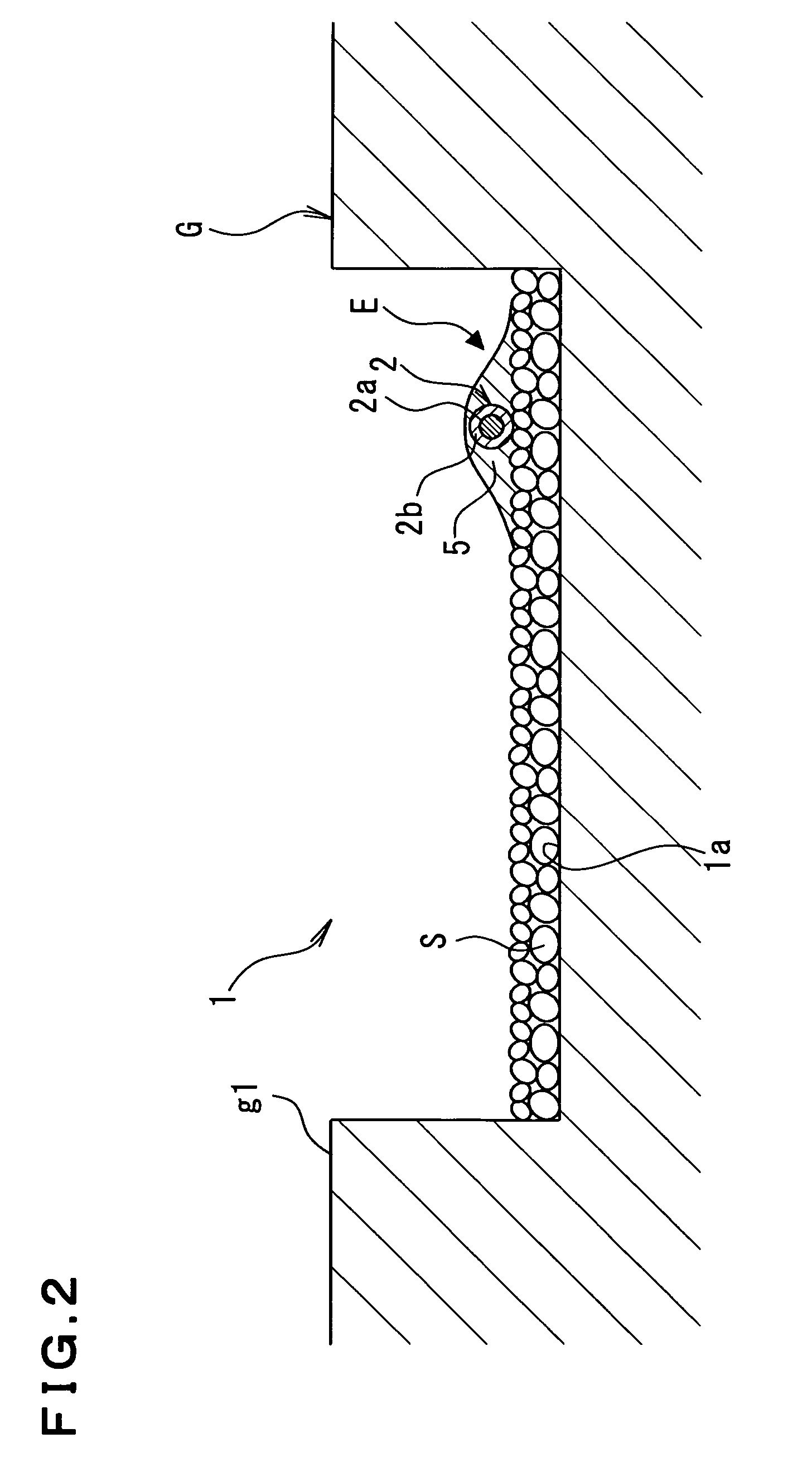
[0019]1 is a ditch drilled in the earth G, and cobble stones S are laid at a bottom portion 1a of the drilled ditch 1, as required.

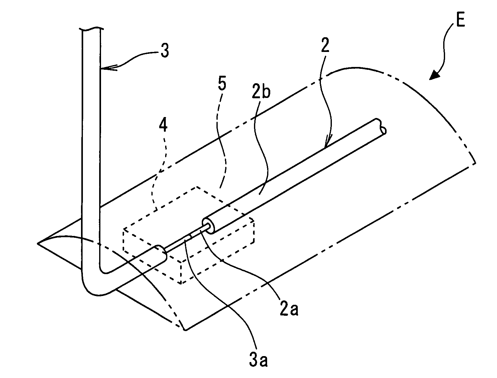
[0020]2 is a grounding conductor. The grounding conductor 2 has a conductive metal line 2a placed in a central portion. The conductive metal line 2a is covered with a conductive resin layer 2b composed of resin mixed with conductive carbon black powder or conductive metal powder.

[0021]The grounding conductor 2 of a predetermined length is installed directly at the bottom portion 1a of the drilled ditch 1 or via the cobble stones S. A conductive covering cap or the like is fitted around one end of the grounding conductor 2 to waterproof this end, and the conductive resin layer 2b is peeled off from the other end of the grounding conductor 2 to expose the con...


PUM


Abstract

The present invention relates to a grounding device in which a grounding member E having a grounding conductor 2 and a conductive laminated portion 5 covering the grounding conductor 2 is integrated with a foundation member B of a building so that the grounding member E and the foundation member B overlap partly or entirely. The grounding device is configured so that the grounding member having the grounding conductor and the conductive laminated portion covering the grounding conductor is integrated with the foundation member of the building are so that the grounding member and the foundation member overlap partly or entirely. This makes it possible to easily offer a small grounding resistance. Further, the foundation member of the building contacts the earth over a large area. This enables a small grounding resistance to be stably offered for a long period.

Description

FIELD OF THE INVENTION[0001]The present invention relates to a grounding device installed in a foundation portion of a building such as a house or a factory and a method of constructing the grounding device.BACKGROUND OF THE INVENTION[0002]A grounding device for use in a building such as a house or a factory is an elongate grounding bar composed of a conductive metal material and driven into vacant land in the premise. Such a grounding device and a method of constructing the grounding device are disclosed in, for example, the Unexamined Japanese Patent Application Publication (Tokkai-Hei) No. 5-182701.[0003]The conventional method of constructing a grounding device requires the check of a site into which the grounding bar is to be driven and the nearby earth for objects buried in these places before the driving of the grounding bar. Thus, the absence of buried objects must be confirmed before the grounding device can be constructed. This disadvantageously results in the need for muc...

Claims


Application Information

Patent Timeline
Patent Type & Authority Patents(United States)
IPC IPC(8): H05K5/02
CPCH02G9/04H02G9/02
Inventor OKABAYASHI, CHIKASHIISHIZAKI, MAKOTOYONEDA, MINORU
Owner SANKOSHA CORP
Why Eureka
Try Eureka