
Light guide sheet and movable contact unit and switch using the same

a technology of movable contact unit and light guide sheet, which is applied in the direction of static indicating device, lighting and heating apparatus, instruments, etc., can solve the problems of unfavorable lighting, more complex structure, and high cost, and achieve the effect of simple structure, cheap cost price and simplified structur

Inactive Publication Date: 2009-11-17
PANASONIC CORP
View PDF11 Cites 14 Cited by
  • Summary
  • Abstract
  • Description
  • Claims
  • Application Information

AI Technical Summary

Benefits of technology

[0018]To solve the conventional problems the present invention aims at providing a light-guide-sheet with a simplified structure free from uneven illumination and a cheap cost price, and a movable-contact-unit and a switch using the same.
[0019]The light-guide-sheet of the present invention comprises a light-guide-member including: an inlet; a generally strip-shaped guide-path coupled with the inlet; and light-emitters coupled with the guide-path, each formed from a polymer having an index of refraction different from that of base-film and formed in grooves provided on one surface side of a base-film. Since the light-emitting-element illuminates the light-guide-member only in the light-guide-sheet, one single light-emitting-element can perform the illumination free from unevenness, which can provide the light-guide-sheet with a simplified structure and a cheap cost price.
[0020]The light-guide-sheet of the present invention has the inlets and light-emitters both shaped irregularly, which enables the light emitted from the light-emitting-element to enter into the light-paths and to illuminate light-emitters themselves brightly by reflecting the light at the inlets and at the light-emitters.
[0021]Moreover, the movable-contact-unit of the present invention has a plurality of generally dome-shaped movable contacts formed of electrically conductive thin metal sheet bonded on the bottom surface of the light-guide-sheet, which provides the movable-contact-unit with a simplified structure free from uneven illumination and a cheap cost price.
[0022]Moreover, the switch of the present invention has a movable-contact-unit bonded on the top surface of a substrate on which a plurality of stationary contacts are provided facing a movable contact to provide the switch with a simplified structure and a cheap cost price
[0023]As described above, the present invention can realize the light-guide-sheet with a simplified structure free from uneven illumination and a cheaper cost price and a movable-contact-unit and switch using the same.

Problems solved by technology

However, in the aforementioned light-guide-sheet and the switch using the same, light-emitting-element 5 is to illuminate the overall light-guide-layer 1A of light-guide-sheet 1, which causes light-emitters 1D located far away from light-emitting-element 5 to become darker due to decrease in light intensity, which tends to cause an uneven illumination.
To reduce the unevenness for a more uniform illumination, many light-emitting-elements are necessary to dispose on the periphery of light-guide-sheet 1 which causes problems of a more complex structure and expensiveness.

Method used


Image

  • Light guide sheet and movable contact unit and switch using the same
  • Light guide sheet and movable contact unit and switch using the same
  • Light guide sheet and movable contact unit and switch using the same

Examples


embodiment

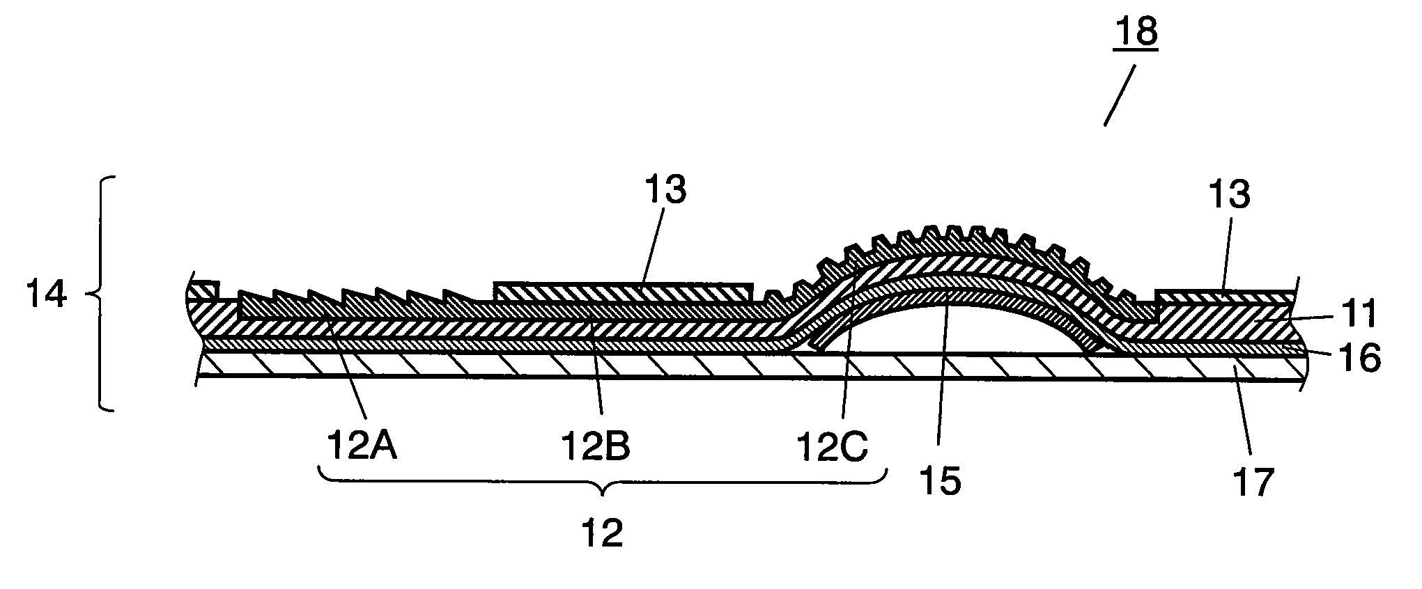
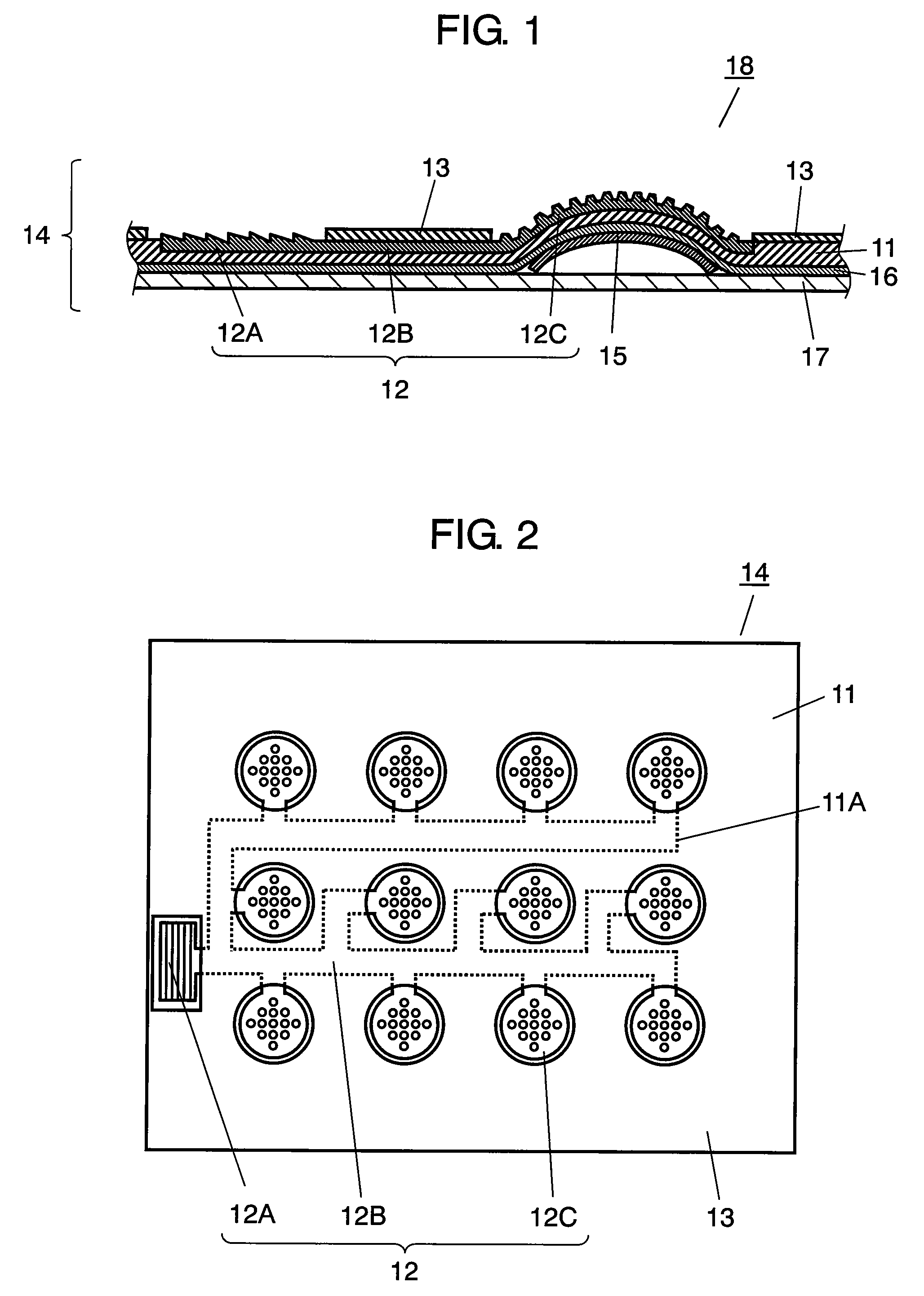
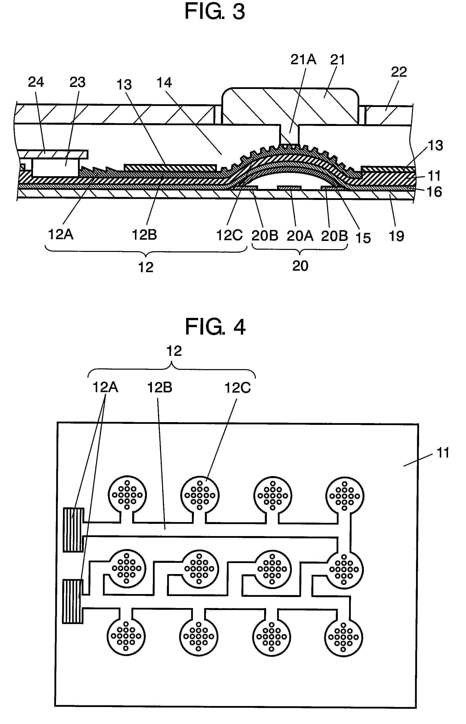
[0031]FIG. 1 is a cross-sectional view of movable-contact-unit 18 used in the preferred embodiment of the present invention, FIG. 2 is a plan view of the light-guide-sheet used in movable-contact-unit 18. In the drawings, base-film 11, with a thickness of 25 to 250 μm and an index of refraction of 1 to 2, is formed from a polymer such as silicone, urethane, polycarbonate or polyethylene-terephthalate series, and a plurality of coupled grooves 11A are provided on the top surface of base-film 11.

[0032]Light-guide-member 12 formed from a polymer similar to a material of base-film 11 and with the index of refraction different from that of base-film 11 is provided in grooves 11A on base-film 11, which includes: inlet 12A; a plurality of strip-shaped guide-path 12B coupled with inlet 12A; and a plurality of generally circular light-emitters 12C coupled with guide-paths 12B.

[0033]Cover film 13 is bonded on the top surface of base-film 11, exposing inlet 12A and light-emitters 12C, and the ...


PUM


Abstract

The disclosed relates to a light-guide-sheet used in operation panel of a various electronic equipment, and a movable-contact-unit and a switch using the same, which have a simplified structure free from uneven illumination and a cheap cost price. Therefore, the light-guide-sheet is provided with the light-guide-member including an inlet, a generally strip-shaped guide-path coupled with the inlet, and generally circularly and irregularly shaped light-emitters coupled with the guide-path, each formed from a polymer having an index of refraction different from that of base-film and formed in grooves provided on a base-film.

Description

CLAIM OF PRIORITY[0001]This application claims the benefit of Japanese Patent Application No. JP 2007-038995, filed on Feb. 20, 2007 the disclosure of which is incorporated herein by reference.FIELD OF THE INVENTION[0002]The present invention relates to a light-guide-sheet used in operation panel of various electronic equipment, and a movable-contact-unit and a switch using the same.BACKGROUND OF THE INVENTION[0003]In recent years, an increasing number of users require various electronic equipment especially mobile devices such as cellular phones capable of identifying and operating switches, push-buttons or the like even in dark surroundings by lighting LEDs, EL elements or the like to illuminate the operation panel for a high usability with a cheep price.[0004]The light-guide-sheet and switch using the same for use in such illumination is described with reference to FIGS. 5 and 6. The drawings are shown on an expanded scale in a thickness direction for an easy understanding.[0005]...

Claims


Application Information

Patent Timeline
Patent Type & Authority Patents(United States)
IPC IPC(8): H01H9/00
CPCH01H13/83H01H13/7006H01H2231/022H01H2219/044H01H2219/062H01H2205/004G02B6/00H04M1/22H01H13/70
Inventor INOUE, TAKEFUMI
Owner PANASONIC CORP
Learn More