Ring configuration for compact power supply of power electronics

a power electronics and compact technology, applied in the field of power electronics, can solve the problems of residual (parasitic) inductance, instabilities and oscillations, adversely affecting performance, etc., and achieve the effect of reducing emi and rfi electrical noise and allowing coolant flow

Inactive Publication Date: 2009-11-17
HENNESSY MICHAEL J +3
View PDF7 Cites 24 Cited by
  • Summary
  • Abstract
  • Description
  • Claims
  • Application Information

AI Technical Summary

Benefits of technology

[0016]In the housing 90, FIG. 9, a vented grounded cylinder or screen 91 surrounds the circuits 80 (as shown in FIG. 8) to reduce EMI and RFI electrical noise, and allows coolant flow. The screen 91 also serves as a safety cover at ground potential. All busses (outputs, V+, V−, ground) interface with external power sources through a coaxial lead 92. In three phase systems output comes out on a triax or quadax lead. There is room for electrical filter networks on ground plates 93 on the top and bottom of the assembly 80 within the ground screen 91.

Problems solved by technology

A key factor that adversely affects performance is the residual (parasitic) inductance in the loop between the voltage bus and the output bus.
This residual inductance can cause instabilities and oscillations (ringing), particularly at high switching speeds.

Method used


Image

  • Ring configuration for compact power supply of power electronics
  • Ring configuration for compact power supply of power electronics
  • Ring configuration for compact power supply of power electronics

Examples


Embodiment Construction

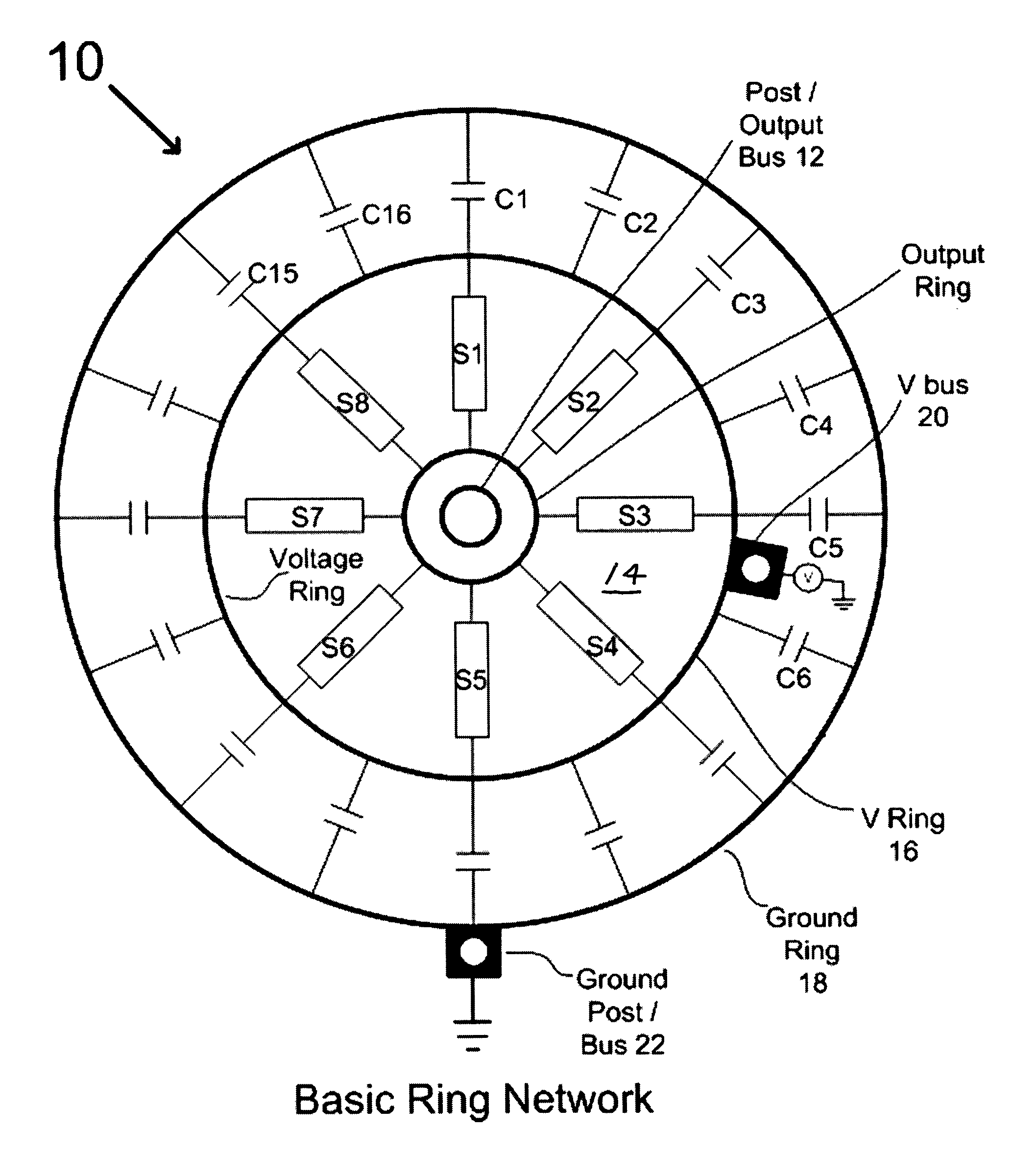
There are several preferred embodiments for this invention. All share in common a circular arrangement of power devices (MOSFETs, IGBTs, etc.) around a central output post.

[0027]In general, similar power switches (e.g. FIG. 2) are arranged in symmetric patterns (like radial spokes) around the output post bus 12 so that each switch is equivalent and performs identically. This requires that each switch in a symmetric pattern is closely matched to the others in performance. Switches are supplied with voltage from a surrounding voltage ring 16, which is concentric with the output bus 12 and filtered (decoupled) via capacitors placed between the voltage ring 16 and a ground ring 18 (or virtual ground ring). The virtual ground (not shown) is not necessarily at DC ground potential but is a good AC ground. It could be another bus at a fixed voltage.

[0028]The surrounding voltage ring 16 is an electrically conductive ring tied to one (or several) electrically conductive vertical posts 20 for ...


PUM

PropertyMeasurementUnit
voltageaaaaaaaaaa
superconductiveaaaaaaaaaa
cryogenic temperatureaaaaaaaaaa

Abstract

An ultra compact ring topology puts the output terminals of solid state switches physically at the center of a circuit with the switches surrounded by voltage busses. The switches are symmetrically arranged around the output bus, the voltage busses are filtered (decoupled) to ground using symmetrically positioned filter components, and lead lengths to and from the switches are minimized. Switch driver circuits are closely integrated with each switch and positioned as close as possible, each to its associated switch, and arranged symmetrically. Switches may be at cryogenic temperatures and busses and lead connectors may be superconductive.

Description

[0001]This patent application claims the benefit of provisional patent application 60 / 609,149, filed Sep. 11, 2004.BACKGROUND OF THE INVENTION[0002]In the realm of power electronics, many topologies require symmetric and anti-symmetric switches as building blocks for motor controllers, inverters, converters, etc., some of which are shown schematically in FIGS. 1A-1D. By switches is meant electrically controlled switches such as solid state switches, i.e., transistors, MOSFETs, IGBTs, etc., or other devices on the developmental horizon. A key factor that adversely affects performance is the residual (parasitic) inductance in the loop between the voltage bus and the output bus. This residual inductance can cause instabilities and oscillations (ringing), particularly at high switching speeds.SUMMARY OF THE INVENTION[0003]To address the issue of residual inductance, the present invention provides an ultra compact ring topology, which puts the output terminals of the switches physically ...

Claims


Application Information

Patent Timeline
Patent Type & Authority Patents(United States)
IPC IPC(8): H01B7/30
CPCH02M7/003H02M3/00H02M3/003
Inventor HENNESSY, MICHAEL J.MUELLER, OTWARD M.MUELLER, EDUARD K.PARK, JOHN N.
Owner HENNESSY MICHAEL J
Why Eureka
Try Eureka