Elastic wave duplexer

a duplexer and elastic wave technology, applied in the field of elastic wave duplexers, can solve the problem of rare deterioration of isolation characteristics, and achieve the effect of improving isolation characteristics, improving isolation characteristics, and improving isolation characteristics

a duplexer and elastic wave technology, applied in the field of elastic wave duplexers, can solve the problem of rare deterioration of isolation characteristics, and achieve the effect of improving isolation characteristics, improving isolation characteristics, and improving isolation characteristics

US7619491B2Active Publication Date: 2009-11-17MURATA MFG CO LTD

Image

  • Elastic wave duplexer
  • Elastic wave duplexer
  • Elastic wave duplexer

Examples


Embodiment Construction

[0051]Preferred embodiments of the present invention are described below with reference to the accompanying drawings.

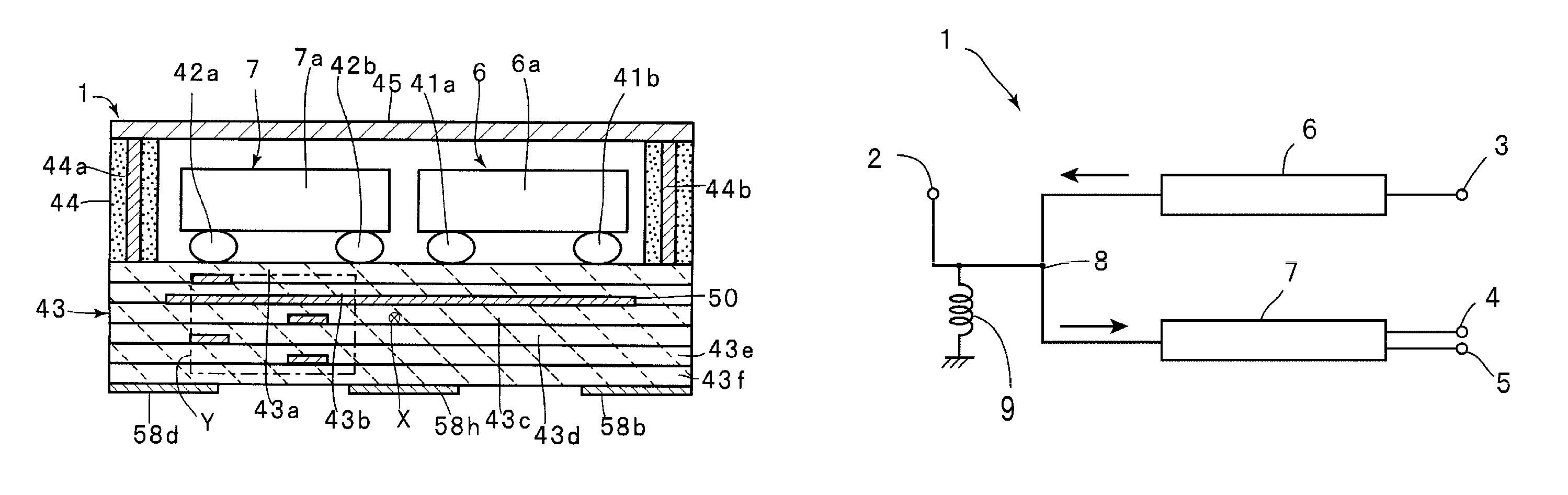
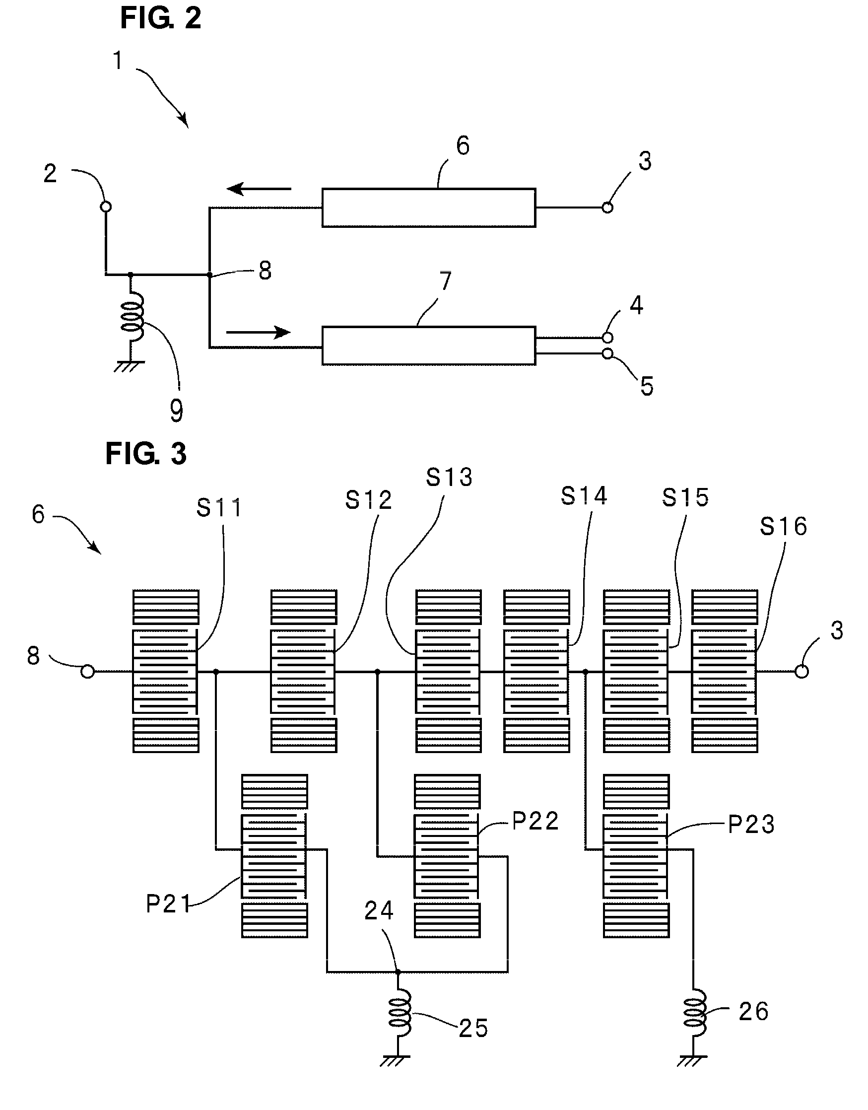
[0052]FIG. 2 is a block diagram of an elastic wave duplexer according to a preferred embodiment of the present invention. According to the present preferred embodiment, an elastic wave duplexer 1 is a duplexer for CDMA800. For a CDMA800 duplexer, the transmission passband ranges from about 824 MHz to about 849 MHz, and the reception passband ranges from about 869 MHz to about 894 MHz.

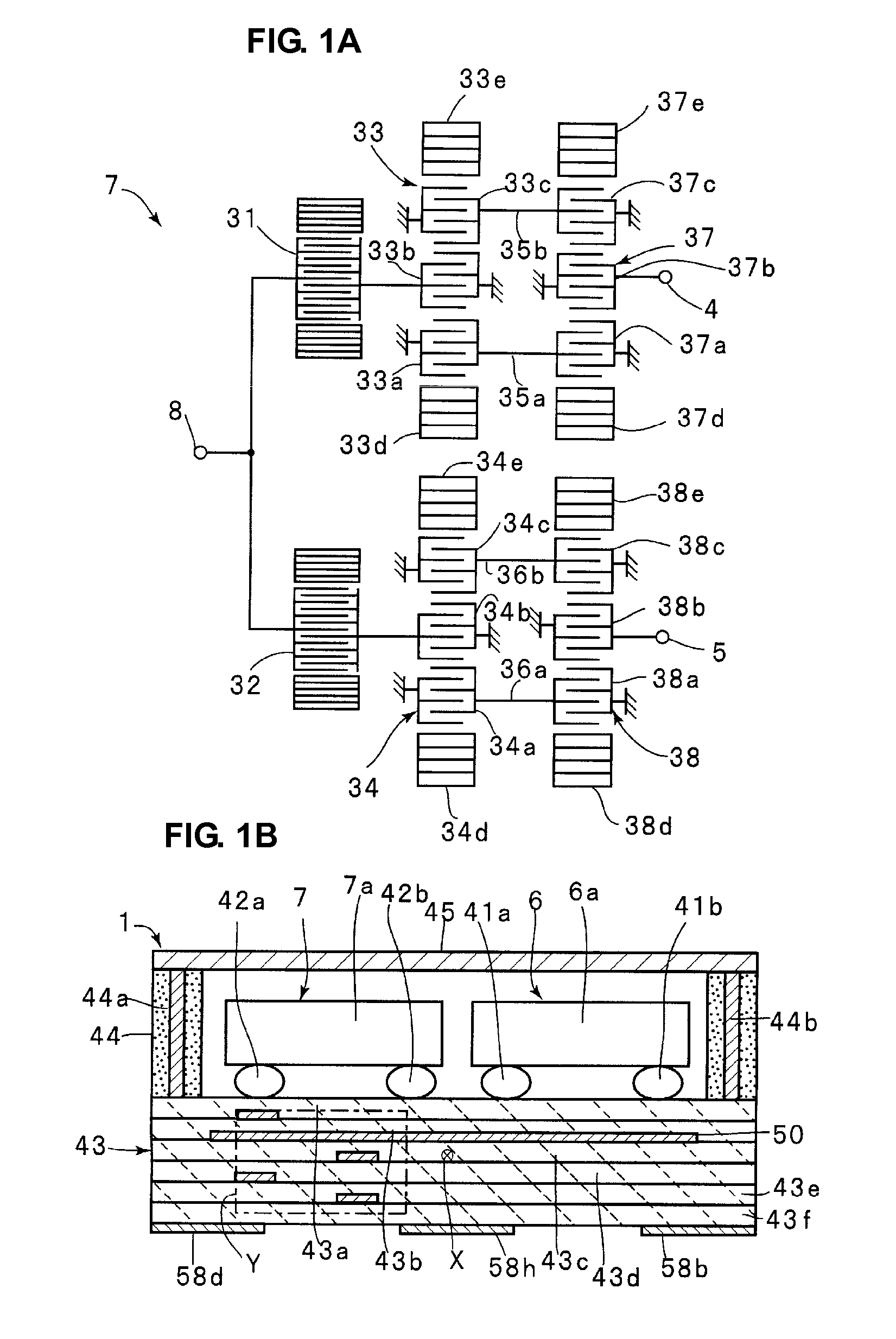
[0053]The elastic wave duplexer 1 includes an antenna terminal 2 connected to an antenna, a transmission terminal 3, a first reception terminal 4, and a second reception terminal 5. One end of a transmission filter chip 6 and one end of a reception filter chip 7 are connected to the antenna terminal 2. The other end of the transmission filter chip 6 defines the transmission terminal 3. The other end of the reception filter chip 7 defines the first reception terminal 4 and the second recep...


PUM


Abstract

An elastic wave duplexer includes a transmission filter chip and a reception filter chip each defined by an elastic wave filter chip and flip-chip bonded to a laminated board. A coil-shaped line including coil-shaped line patterns is provided inside the laminated board. The coil-shaped line defines an impedance matching circuit. In plan view, the transmission filter chip is disposed on one side of a center line passing through the approximate center of the laminated board and extending between a first edge and a second edge, and the reception filter chip is disposed on the other side of the center line. The coil-shaped line is disposed on the side on which the reception filter chip is disposed.

Description

BACKGROUND OF THE INVENTION[0001]1. Field of the Invention[0002]The present invention relates to an elastic wave duplexer including an elastic wave filter, such as a surface acoustic wave filter or a boundary elastic wave filter, and, in particular, to an elastic wave duplexer having including a transmission filter chip and a reception filter chip that are flip-chip bonded to a laminated board using a face-down technique.[0003]2. Description of the Related Art[0004]For mobile communication devices, such as cell phones, in order to reduce the size, the demand for a composite electronic component including a plurality of electronic components integrated therein is increasing. To meet such a demand, a duplexer including a transmission filter and a reception filter integrated therein has been commonly used. The transmission filter and the reception filter are connected to an antenna terminal. In addition, to reduce the size of the filters, surface acoustic wave filters using surface aco...

Claims


Application Information

Patent Timeline
17 Nov 2009
Publication
US7619491B2
IPC
H03H9/72; H03H9/64
CPC
H03H9/0576; H03H9/725; H01L2224/16; H01L2224/48227; H01L2224/49171; H01L2924/00; H01L2924/30111
Inventors
TAKATA, TOSHIAKI; YOKOKURA, OSAMU