Optically amplified critical wavelength refractometer

a critical wavelength, refractometer technology, applied in the direction of optical radiation measurement, instruments, spectrometry/spectrophotometry/monochromators, etc., can solve the problems of limiting the overall in-situ accuracy to the 10sup>6/sup>range, mechanical nature of angular measurements, and limiting the overall in-situ accuracy. to the effect of enhancing the sensitivity of the sensing beam

Inactive Publication Date: 2009-11-17
SEALITE ENG
View PDF8 Cites 10 Cited by
  • Summary
  • Abstract
  • Description
  • Claims
  • Application Information

AI Technical Summary

Benefits of technology

[0010]In another aspect of the invention, a beam splitter is interposed between the broadband light source and the sensor, the beam splitter dividing the incident light into a reference beam and a sensing beam. The sensing beam is coupled to the sensor where it undergoes multiple internal reflections against the sensing surface(s). The reference beam does not interact with the external material or the sensing surface(s), thereby providing a means for monitoring intensity and / or spectral variations in the output of the light source. The reference beam can be coupled to a second detector, e.g., a spectrograph, or multiplexing can be used to couple both the sensing beam and the reference beam to a single detector. Preferably a polarizing beam splitter is used, thus further enhancing the sensitivity of the sensing beam.

Problems solved by technology

In the 1980's an in-situ device was made based on this principle which used a solid-state beam-position indicator and was accurate to the sixth decimal place; however, the mechanical nature of angular measurements make them subject to errors from oceanic pressure and temperature changes.
Unfortunately, this parameter cannot be easily measured.
As these interferometric methods measure the index of refraction relative to a fixed value in the reference beam, pressure and temperature changes can affect the result and thus limit the overall in-situ accuracy to the 10−6 range.
Although all of the afore-described techniques provide means for measuring the index of refraction of seawater, none of them provide the desired level of accuracy for an in-situ oceanographic instrument.

Method used


Image

  • Optically amplified critical wavelength refractometer
  • Optically amplified critical wavelength refractometer
  • Optically amplified critical wavelength refractometer

Examples


Embodiment Construction

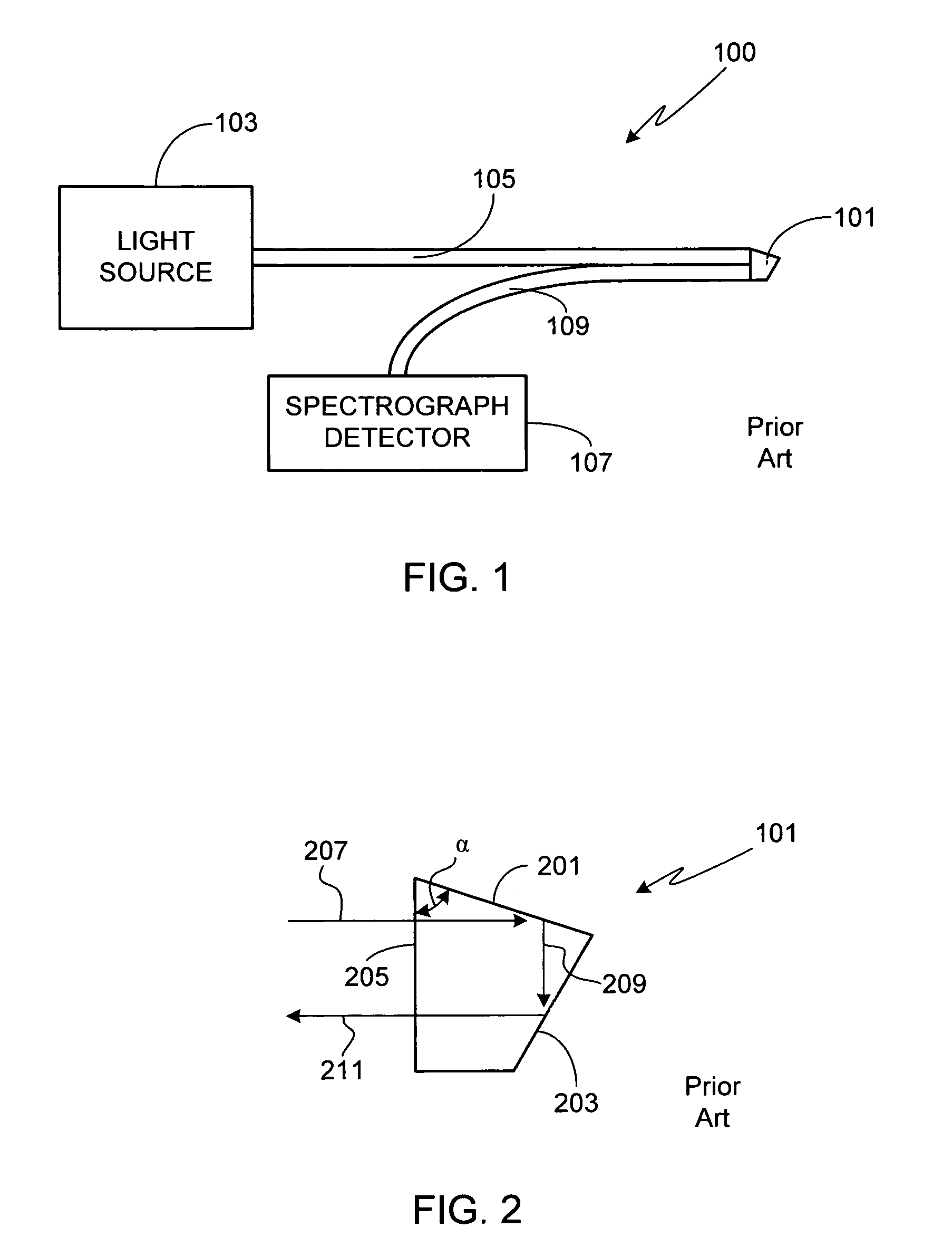
[0020]FIG. 1 is an illustration of a critical wavelength refractometer in accordance with the prior art, a full description of which is provided in U.S. Pat. No. 4,699,511, entitled Refraction Sensor, the specification of which is incorporated herein. As shown, refractometer 100 is comprised of a probe that includes a prism-shaped sensor 101. Sensor 101 is coupled to a broadband white radiant energy light source 103 by at least one optical fiber 105, and coupled to a spectrograph detector 107 by at least one optical fiber 109.

[0021]As shown in detail in FIG. 2, prism-shaped sensor 101 includes a ground and polished sensing face 201, a mirrored reflecting face 203, and an incident face 205. Angle α, measured between faces 201 and 205, is chosen along with the wavelength range of light source 103 and the material comprising the prism-shaped sensor 101 to cover the index of refraction range of interest for the material to be monitored, i.e., the material in contact with sensing face 20...


PUM

PropertyMeasurementUnit
thickaaaaaaaaaa
critical wavelengthaaaaaaaaaa
lengthaaaaaaaaaa

Abstract

A critical wavelength refractometer is provided. A broadband light source (413) is optically coupled to a sensor (401), the sensor having at least one sensing surface (407). As the light from the broadband light source passes through the sensor, it undergoes multiple internal reflections against the sensing surface. Due to the index of refraction of the material in contact with the sensing surface, a portion of the light passing through the sensor is reflected while a second portion of the light is transmitted through the sensing surface and into the material. A detector (421) coupled to the sensor measures the spectral intensity of the light that passes completely through the sensor after having undergone the multiple internal reflections against the sensing surface. A microprocessor (423) coupled to the detector determines the critical wavelength based on the spectral intensity measurement, thereby allowing the index of refraction of the material to be determined.

Description

FIELD OF THE INVENTION[0001]The present invention relates generally to index of refraction sensors and, more particularly, to a critical wavelength refractometer.BACKGROUND OF THE INVENTION[0002]Physical oceanography studies have used the index of refraction as a means of determining the density of seawater for decades, although only recently have practical instruments with suitable accuracy been developed. In general terms, these instruments use one of three refractometry principles; critical reflection measurements at a single wavelength, speed of light measurements at a single wavelength, and critical reflection measurements using a broadband source.[0003]In conventional refractometers, the variation of the critical angle is measured as a function of the external index of refraction, the measurement being performed using a monochromatic source. This method, generally accurate to the fifth decimal place, is used in commercial laboratory instruments as well as in industrial process...

Claims


Application Information

Patent Timeline
Patent Type & Authority Patents(United States)
IPC IPC(8): G01N21/41
CPCG01N21/4133G01N21/43G01N2021/438G01N2021/434G01N21/431
Inventor SEAVER, GEORGE A.
Owner SEALITE ENG
Why Eureka
Try Eureka