Authentication mechanisms for call control message integrity and origin verification

a call control and authenticity technology, applied in the field of authenticity mechanisms for call control message integrity and origin verification, can solve the problems of increasing message processing time, affecting the implementation of ssm, and complex snmp portion of fr ssm than its atm counterpar

Active Publication Date: 2009-11-17
ALCATEL-LUCENT USA INC
View PDF13 Cites 241 Cited by
  • Summary
  • Abstract
  • Description
  • Claims
  • Application Information

AI Technical Summary

Problems solved by technology

Third, it generates SNMP get requests to obtain keys not in the SAD.
Since FR does not have an existing SNMP-based state machine like ILMI, the SNMP portion of the FR SSM is much more complex than its ATM counterpart.
Two classes of issues may negatively impact SSM implementations.
First, SSM processing may increase message processing times, negatively impacting message processing speed and control plane throughput.
Second, call rejection associated with security restrictions may negatively affect routing algorithms and procedures.
If the authentication portion becomes too large, protocol timers may time out, leading to retransmission of requests and acerbating switch congestion.
First, SPD and SAD access may require a considerable amount of time relative to protocol timers.
Second, computation of the MD5 digest is computationally intensive.
Because SSM functions as a shim layer protocol with its own databases, it does not directly affect control or user plane routing protocols; however, authorization failures may indirectly impact routing efficiency.
This is one of the strengths of the SSM approach; however, there are two issues that may arise.
First, if there is no set of SAs between the calling and called party, several crankback iterations may occur, negatively impacting the performance of the intermediate system attached to the calling party.
Second, if the call fails due to authorization failure, the intermediate system attached to the calling party may delete the called party's intermediate system from its routing tables.

Method used


Image

  • Authentication mechanisms for call control message integrity and origin verification
  • Authentication mechanisms for call control message integrity and origin verification
  • Authentication mechanisms for call control message integrity and origin verification

Examples


case 2

[0065]Once the call initiation phase has begun, it is the responsibility of the key authority to flood any key changes to its peers or end systems. In the next six subsections, the state machine for each case will be described in the order in which the state occurs during call initiation. FIGS. 13, 14, and 15 provide a graphical representation of these state machines and their interactions. That is, these figures represent the invention's processing of various key distribution cases. These cases are numbered and described in detail below. These numbers correspond to the numbered paths depicted in the figures. In all signaling and SNMP interactions described below, several underlying assumptions apply. First, all SNMP requests received by an interface must contain the HMAC MD5 digest computed over the entire message, less the digest, with the sender's key. Second, all SNMP requests must be authenticated using the sender's key before being processed. This provides authentication of th...


PUM


Abstract

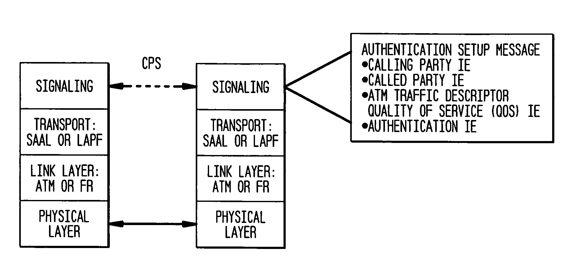
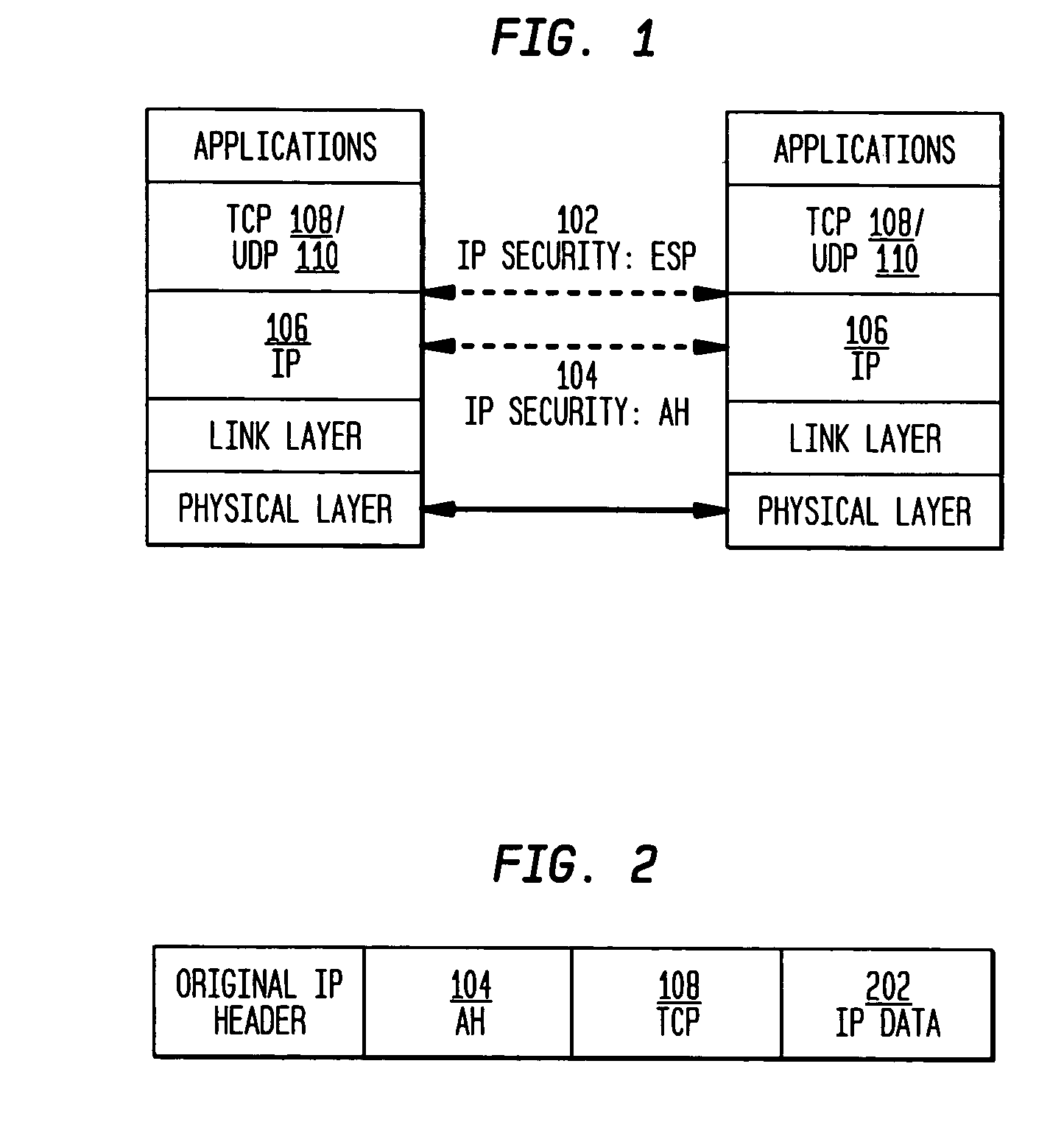
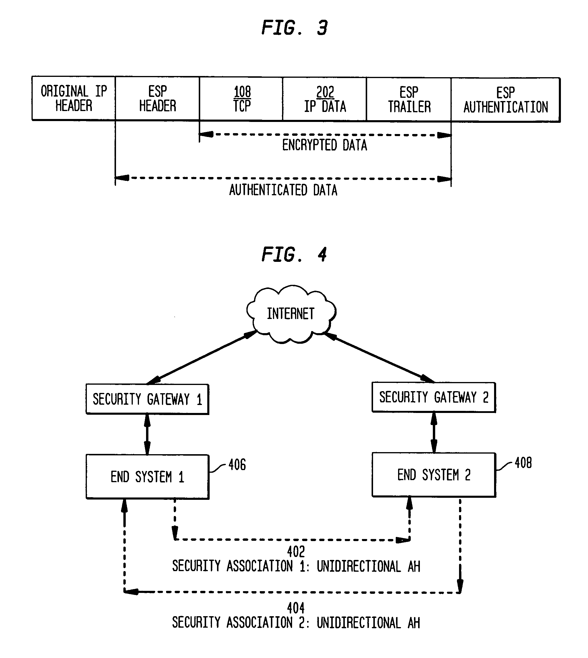
The present invention incorporates methodologies developed in the Internet Engineering Task Force (IETF) Internet Protocol Security (IPSEC) Working Group into asynchronous transfer mode (ATM) and frame relay (FR) signaling to provide message integrity and origin authentication. In one implementation the invention provides a virtual private network (VPN) infrastructure with call control message integrity, origin verification, and transit network filtering. The invention utilizes a set of control plane messages based on the IPSEC authentication header (AH) methodology to provide these security mechanisms for ATM and FR network switching equipment and signaling protocols. This abstract itself is not intended to limit the scope of this patent. The scope of the present invention is pointed out in the appending claims.

Description

TECHNICAL FIELD[0001]The present invention relates generally to utilizing authentication header methodology in providing security mechanisms for asynchronous transfer mode and frame relay network switching equipment and signaling protocols.BACKGROUND[0002]Asynchronous transfer mode (ATM) and frame relay (FR) are deployed extensively as the broadband backbone and Internet protocol (IP) data backhaul, respectively. One purpose of this deployment is to integrate voice and data communications and provide virtual private network (VPN) services to small- and medium-sized business customers. Network service providers are utilizing in-band signaling mechanisms, such as ATM user-network interface version 4.0 (UNI 4.0). Inherent in these mechanisms is the danger of bypassing traditional protection mechanisms, such as firewalls, and exposing sensitive information to global public Internet networks. Providers are also employing classic IP over ATM, local area network emulation, or multiprotocol...

Claims


Application Information

Patent Timeline
Patent Type & Authority Patents(United States)
IPC IPC(8): H04W4/00H04L12/28H04L12/66
CPCH04L12/2854H04L63/164H04L63/0272
Inventor DUNN, JEFFREY H.MARTIN, CYNTHIA E.
Owner ALCATEL-LUCENT USA INC
Why Eureka
Try Eureka