Rod-shaped implant element with flexible section
a technology of flexible section and implant element, which is applied in the field of rod-shaped implant element, can solve the problems of limiting the application of this stabilization apparatus, the known joint fixation apparatus is not suitable for being used on the spinal column, and the stabilization apparatus fails to be torsionally stiff, etc., and achieves the effect of reliable fixation in position with such screws
- Summary
- Abstract
- Description
- Claims
- Application Information
AI Technical Summary
Benefits of technology
Problems solved by technology
Method used
Image
Examples
first embodiment
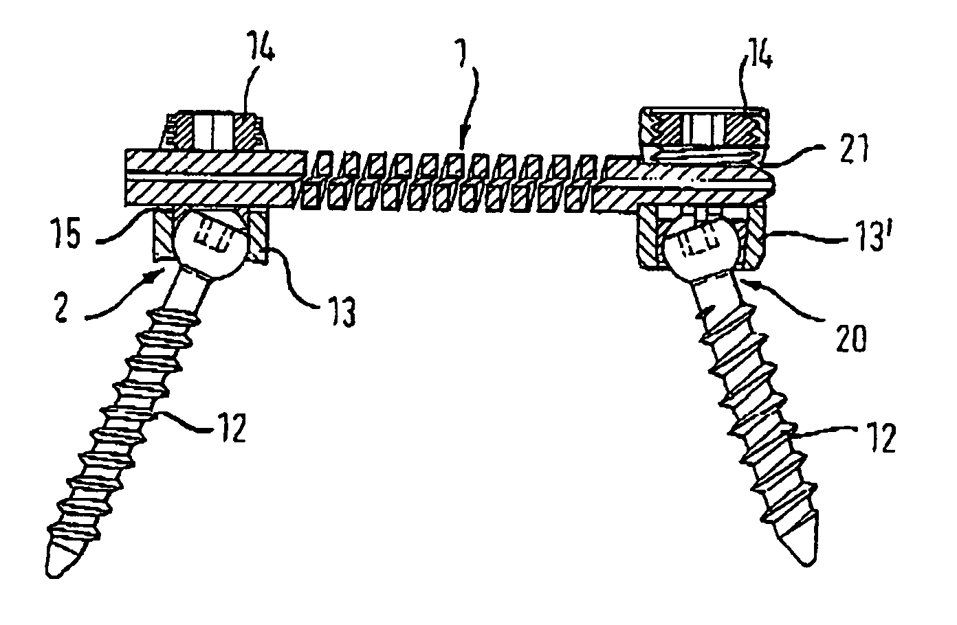
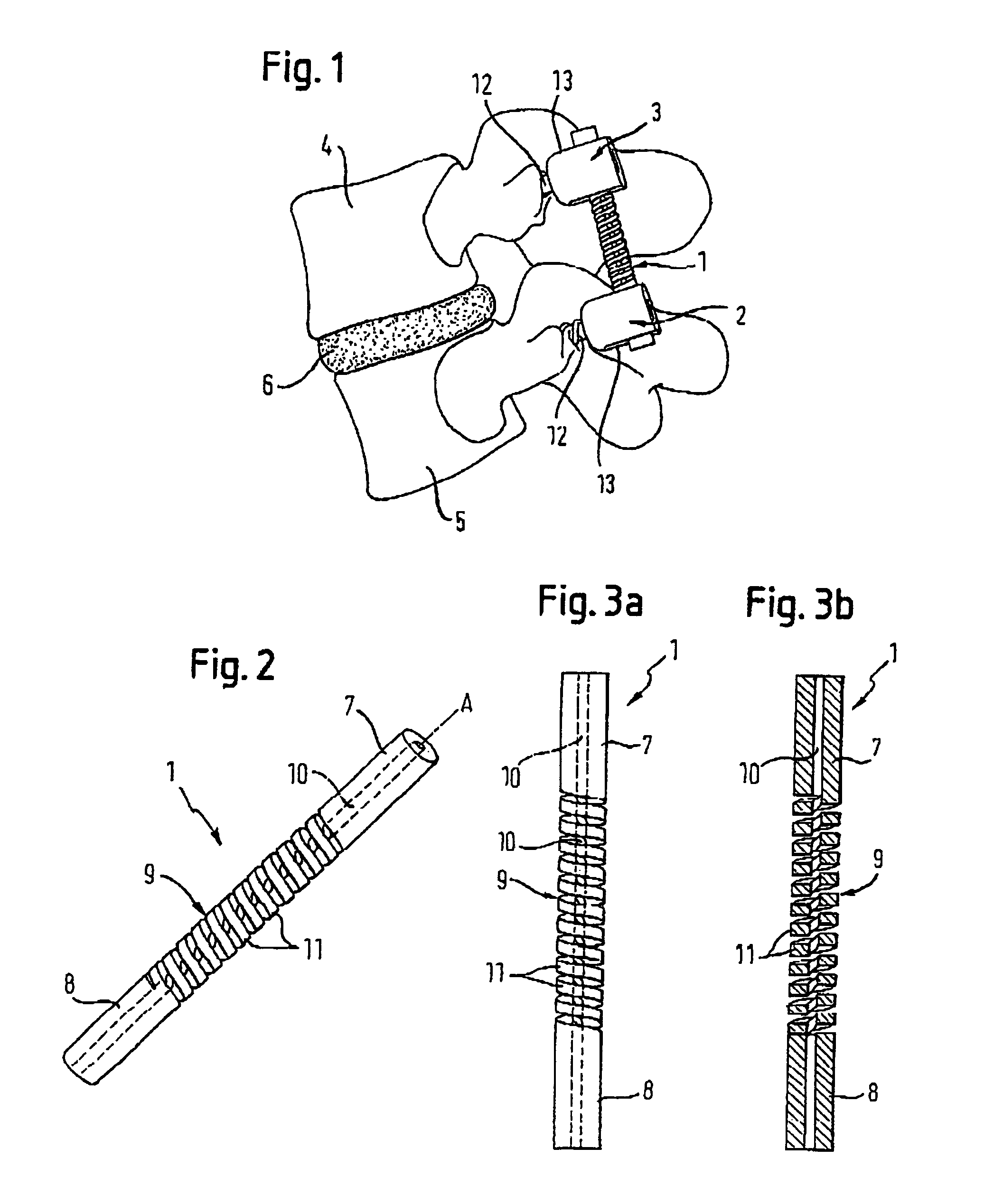
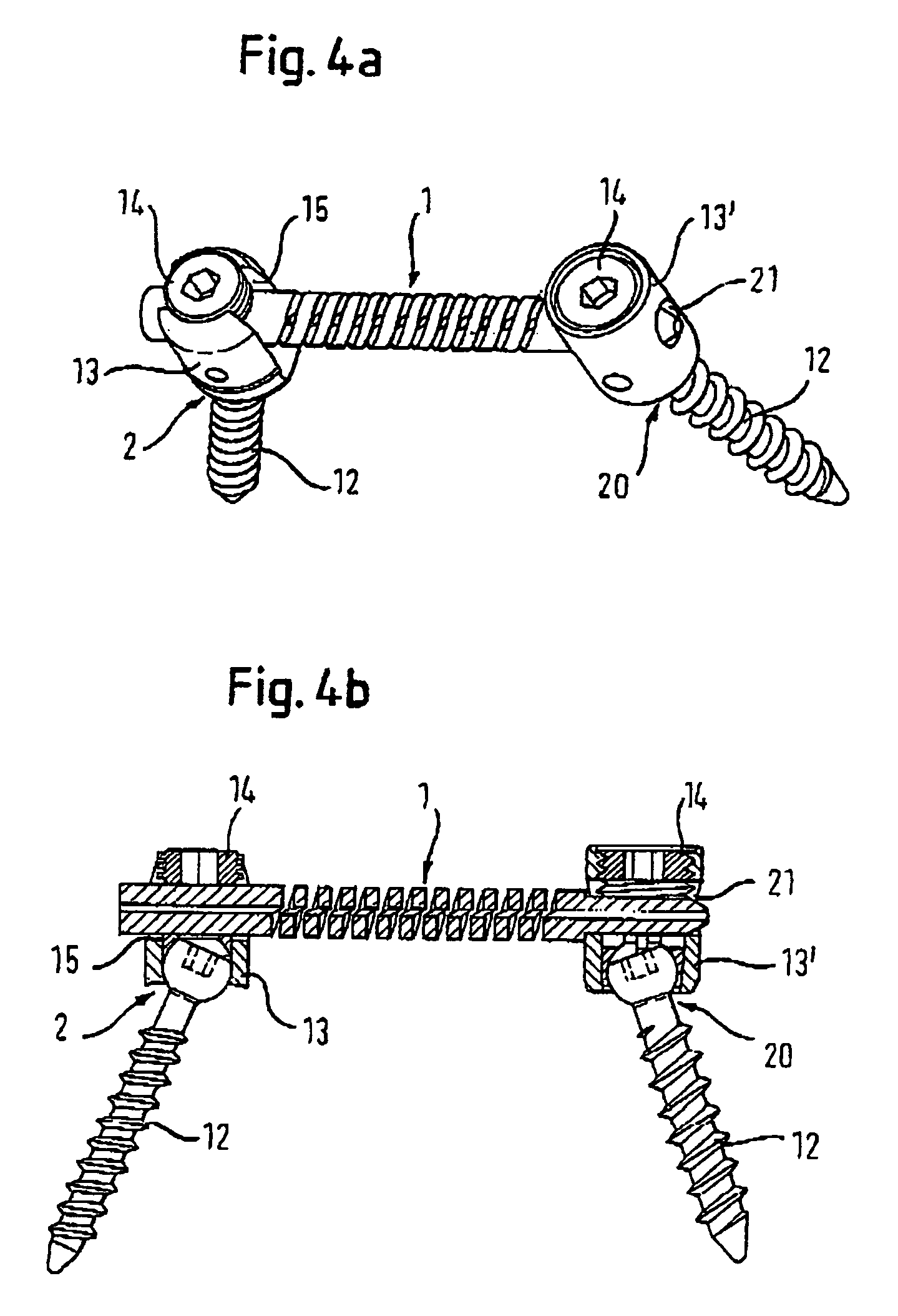
[0057]The rod-shaped implant element 1 according to the invention is designed as a single piece. As shown in FIGS. 2, 3a and 3b, the rod-shaped implant element comprises in a first embodiment a first rigid section 7 that extends across a predefined length from its first end and a second rigid section 8 that extends across a predefined length from its second end as well as a flexible section 9 of predefined length that is provided between the rigid sections 7, 8, with all sections having the same outside diameter. In addition, a coaxial bore 10 of predefined diameter extends through the rod-shaped implant element, The flexible section 9 is designed with a helical slotted opening extending radially from the surface to the coaxial bore 10 with windings 11 of a predefined pitch (a helical groove). The groove can have straight or tap end sides. The height of the windings 11 of the flexible section 9 in the direction of the longitudinal axis A of the rod-shaped implant element, the diamet...
third embodiment
[0063]FIGS. 6 and 7 show a rod-shaped implant element 101 according to a This rod shaped implant element is different from the rod-shaped implant elements 1, 100 of the preceding embodiments in that the flexible section 900 that is provided between the rigid sections 7, 8 comprises two regions 901 that are offset by 180 degrees in relation to each other and are shaped towards the axis of the rod in a concave manner in an arc extending along the axis. The length L of the regions 901 in direction of the rod axis is no more than equal to the length of the flexible section 901, and the bending radius is such that the windings of the helical slotted openings are not interrupted. Due to this form, the flexible section 900 has a “waisted” form (i.e., like the waist of a person) in a direction B that is perpendicular to the rod axis A, thus possessing less stiffness in this direction. This provides an oriented stiffness that is appropriate for certain applications.
[0064]The operation is id...
fourth embodiment
[0065]In a fourth embodiment that is shown in FIG. 8 and 9, the rod-shaped implant element 102 comprises a cylindrical core 110 that extends in coaxial direction through the flexible section 902 and possesses a specific bending flexibility. The diameter of the core 110 is dimensioned such that the core 110, after having been pushed into the bore 10, is truly secured in the latter. Preferably, the core is made of the same material as the rod-shaped implant element, but it may also consist of a second biocompatible material. such as, for example, a flexible plastic material.
[0066]In a modified form, the core 110 is connected to the rigid sections 7, 8 and to the windings of the helical slot flexible section 902 in a single piece. For example, when a core of the same material is desired, it also can be provided by omitting the coaxial bore in the manufacturing of the rod-shaped implant element. As compared with the first embodiment, the core 110 causes a higher bending stiffness of the...
PUM
 Abstract
Description
Claims
Application Information
 - R&D
- Intellectual Property
- Life Sciences
- Materials
- Tech Scout
- Unparalleled Data Quality
- Higher Quality Content
- 60% Fewer Hallucinations
Browse by: Latest US Patents, China's latest patents, Technical Efficacy Thesaurus, Application Domain, Technology Topic, Popular Technical Reports.
© 2025 PatSnap. All rights reserved.Legal|Privacy policy|Modern Slavery Act Transparency Statement|Sitemap|About US| Contact US: help@patsnap.com


