
Power level display calibration device

a technology of power level display and calibration device, which is applied in the direction of circuit monitoring/indication, electric vehicles, transportation and packaging, etc., can solve the problems of unexpected power loss, many users do not periodically fully discharge and recharge their device's batteries, and change the charge capacity of rechargeable batteries over the lifetime of batteries

Inactive Publication Date: 2009-11-24
VINCI BRANDS LLC
View PDF42 Cites 90 Cited by
  • Summary
  • Abstract
  • Description
  • Claims
  • Application Information

AI Technical Summary

Benefits of technology

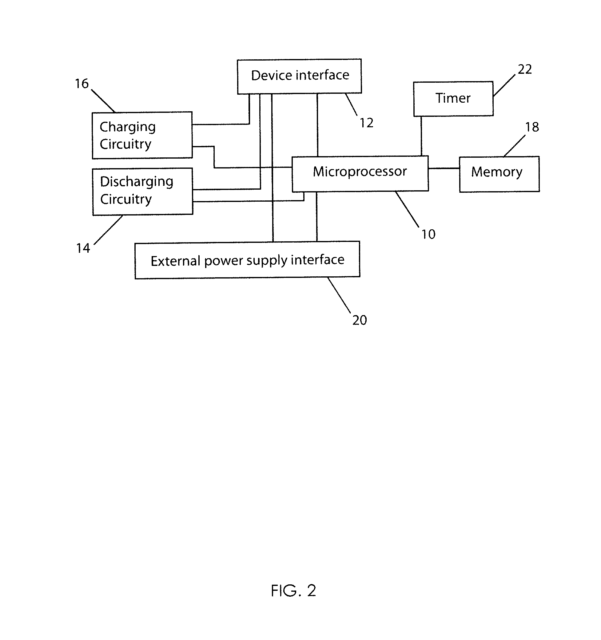
[0006]An embodiment of the present invention is directed toward a charging accessory for a portable electronic device such as a digital music player having an input / output port. The charging accessory includes an input / output port for providing electrical connections to the device's input / output port. The charging accessory has an adapter that is used to receive a power supply voltage from an external power source. A discharging circuit in the charging accessory automatically discharges the battery of the portable electronic device. The discharging may also be accomplished by enabling a power drawing feature of the device. A charger in the charging accessory then charges the battery of the portable electronic device. A processor determines when the device battery is fully charged and fully discharged. Alternatively, the device itself may determine when the battery is fully charged and stop the charging with its power management system or the accessory may simply keep charging until it is disconnected from the device. A display indicates a status of the charging and discharging so that a user can determine when the operation is complete. The processor saves a time stamp associated with the charging / discharging time and device identification information such as a serial number in a memory. The charging accessory can then automatically perform a discharging / charging operation for the device according to a predetermined schedule. The charging accessory may also include a transmitter for broadcasting a signal received from the portable electronic device to a remote receiver.
[0007]Another embodiment of the present invention is directed toward a charging accessory for a portable electronic device. The charging accessory includes an automatic charging and discharging circuit for automatically discharging and charging a battery of a device when the device is connected to the charging accessory to facilitate calibration of a battery level display of the device. The charging accessory includes a processor that determines when the device battery is fully charged and fully discharged. The processor saves a time stamp associated with a charging time and device identification information associated with the particular device being charged in a memory and then automatically performs a discharging / charging operation for the device according to a predetermined schedule whenever the charging accessory is connected to the device.
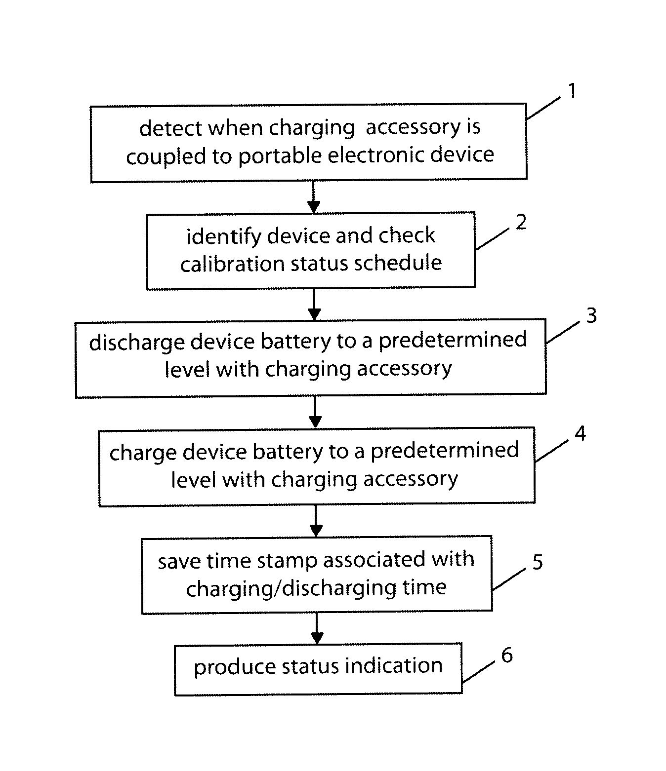
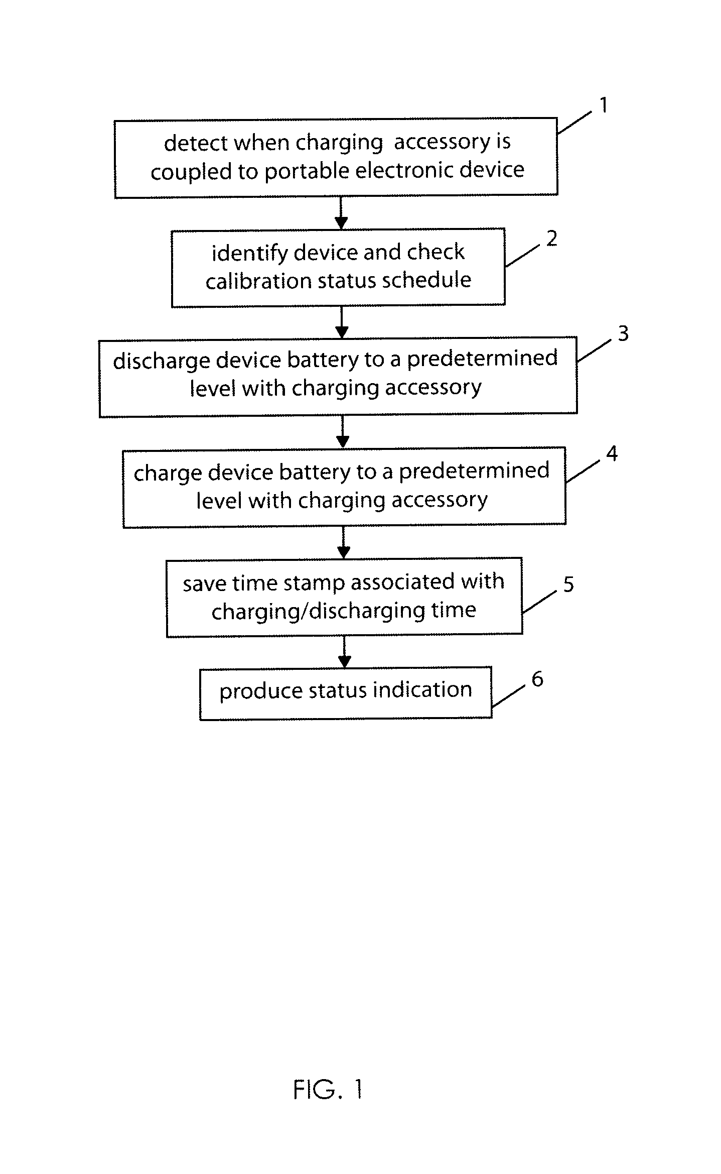
[0008]Yet another embodiment of the present invention is directed toward a method of calibrating a battery level display of a portable electronic device with a charging accessory for the device. The method begins by detecting when the charging accessory is coupled to the portable electronic device. Once the device is detected, the device's battery is automatically discharged to a predetermined level with the charging accessory. The device's battery is then automatically charged to a predetermined level with the accessory. Preferably, the device battery is fully discharged and fully charged. A visual indication of a status of the discharging and charging is produced so that a user can determine when the device is ready to use. A time stamp associated with a charging time may be produced and device identification information and the time stamp stored such that a discharging / charging operation for the device can be automatically performed according to a predetermined schedule.

Problems solved by technology

Unfortunately, the charge capacity of a rechargeable battery changes over the lifetime of the battery.
Unfortunately, many users do not periodically fully discharge and recharge their device's batteries as recommended by battery manufacturers.
This may lead to an unexpected loss of power when a power level display indicates that power remains or the consumer believing that the battery needs charging when in reality it still retains a sufficient charge for operation.
Either situation can lead to a loss of consumer goodwill.

Method used


Image

  • Power level display calibration device
  • Power level display calibration device
  • Power level display calibration device

Examples


Embodiment Construction

[0012]Referring now to FIG. 1, a flowchart of a method of automatically calibrating a power level display of a portable electronic device with a power charging accessory in accordance with an embodiment of the present invention is shown. The method starts in step 1 wherein the charging accessory detects when it is coupled to a portable electronic device. Once the portable electronic device is detected, the charging accessory identifies the particular device to which it is coupled and checks the device's calibration schedule in step 2. This is preferably accomplished by receiving a device identification code from the device and a checking a data file in the charging accessory to see if and when any calibration routines have been performed on the particular device. If a calibration routine has already been recently performed, the charging accessory simply proceeds to charge the device like a normal charger. In addition, the charging accessory may be provided with a user input that all...


PUM


Abstract

A charging accessory for a portable electronic device has an input / output port for providing electrical connections to an input / output port of the device. The accessory includes a charger for charging the battery of the portable electronic device and a discharging circuit for discharging the battery of the device. A processor in the accessory determines when the device battery is fully charged and fully discharged. A time stamp associated with a charging / discharging cycle and device identification information identifying the particular device upon which the charging cycle was performed is stored in a memory of the accessory. The charging accessory then automatically performs a discharging / charging operation for the device according to a predetermined schedule to recalibrate a battery level display of the device whenever the accessory is coupled to the device.

Description

CROSS-REFERENCES TO RELATED APPLICATIONS[0001]Not ApplicableSTATEMENT REGARDING FEDERALLY SPONSORED RESEARCH OR DEVELOPMENT[0002]Not ApplicableREFERENCE TO SEQUENCE LISTING OR COMPUTER PROGRAM LISTING APPENDIX[0003]Not ApplicableFIELD OF THE INVENTION[0004]The invention is generally directed toward the field of power charging accessories for portable electronic devices. More particularly, the present invention is directed toward a device that calibrates a power level reading for a device having a rechargeable power supply.BACKGROUND OF THE INVENTION[0005]A wide variety of modern devices utilize rechargeable batteries. These devices often have a power controller, which may be included in the battery or the device itself, that provides an estimate of the amount of energy in the battery during charging and discharging that is used to produce a power level display or reading. The maximum, minimum, and display changing power levels, i.e. power bars, for the power level display are either...

Claims


Application Information

Patent Timeline
Patent Type & Authority Patents(United States)
IPC IPC(8): H02J7/00
CPCH02J7/0047H02J2007/005H02J7/0048H02J7/0049
Inventor GRIFFIN, PAUL
Owner VINCI BRANDS LLC
Learn More