
Method and apparatus for tomographic multiphase flow measurements

a multi-phase flow and measurement method technology, applied in the field of methods and flow meters, can solve the problems of not meeting the requirements of a three-phase flow meter yet, damage to the interior of the instrument, and high cost of test separators, so as to improve the measurement accuracy and component range.

Active Publication Date: 2009-12-01
FMC KONGSBERG SUS
View PDF44 Cites 34 Cited by
  • Summary
  • Abstract
  • Description
  • Claims
  • Application Information

AI Technical Summary

Benefits of technology

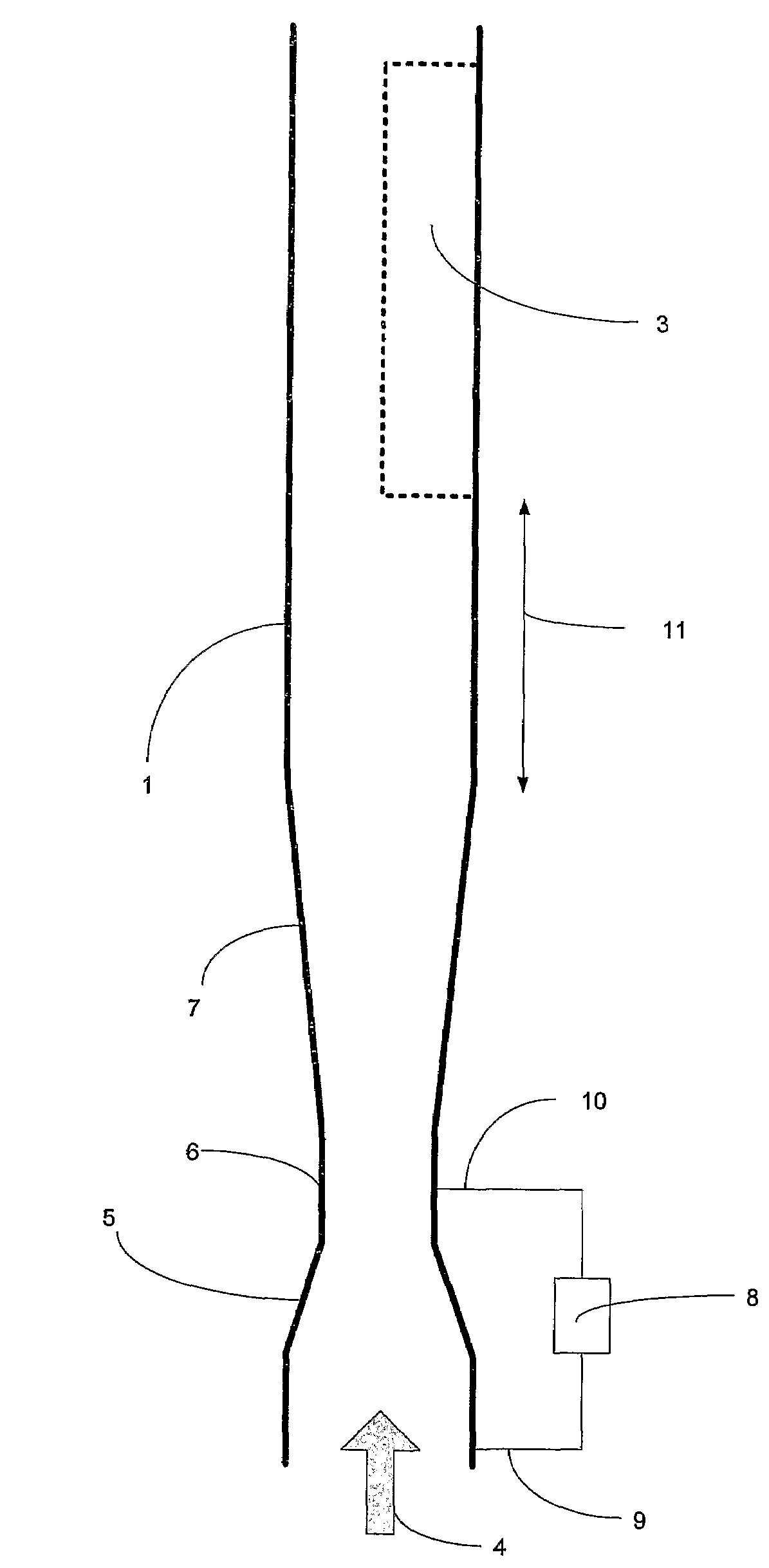
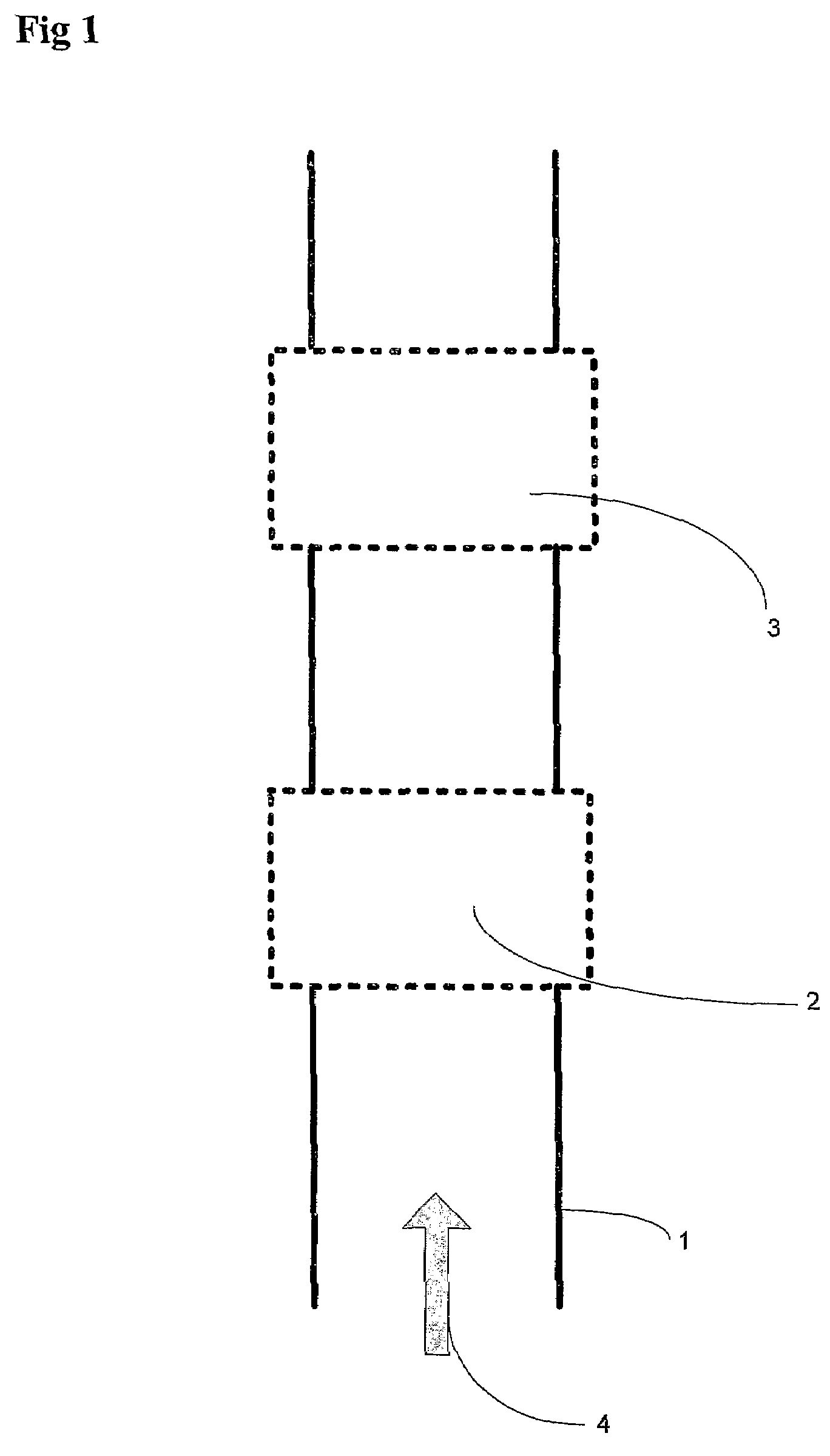
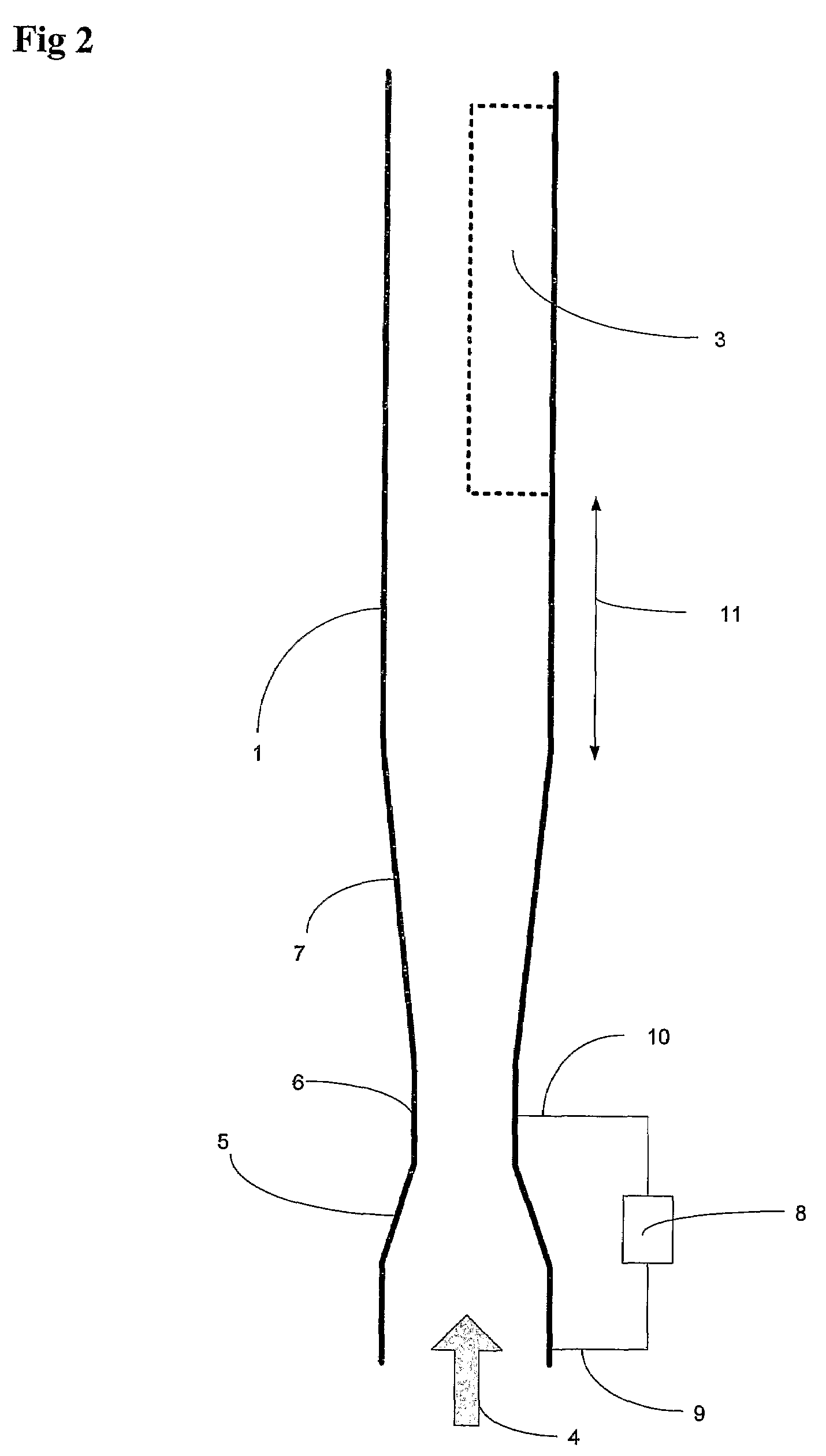
The patent describes a device for measuring the distribution of fractions in a multiphase flow in a vertical tubular section. The device includes a flow conditioning device and a tomographic measurement device. The flow conditioning device generates a symmetrical annular gas concentration flow regime in the vertical tubular section, which is necessary for measuring the individual fractions and distribution of fractions in the entire tubular section. The device can be used in long straight upstream pipe sections and can also be extended by adding a photon source and detector for more accurate measurements. The device can also be used for measuring the dielectric constant / permittivity of the multiphase mixture and can be further extended to improve measurement accuracy and component range.

Problems solved by technology

In spite of the large number of solutions that have been proposed in recent years, no commercially available three phase flow meter yet meets all these requirements.
Inside the pipe, the flowing multiphase fluid may be traveling at a speed of 1-50 m / s with pressures in excess of 1000 bars and temperatures above 200° C. Sand is often also present and can damage the interior of the instrument.
Test separators are expensive, occupy valuable space on a production platform, and require a long time to monitor each well because of the stabilised flow conditions required.
In addition, test separators are only moderately accurate (typically ±5 to 10% of each phase flow rate) and cannot be used for continuous well monitoring.
However, in addition to the disadvantages of the test separator described above, dedicated test pipelines to each well are also required.
Multiphase meters are normally not mounted in a horizontal position due to the presence of laminar flow, where water is in the bottom of the pipe and gas at the top, which would distort the measurement.
However, when the flow is flowing in vertical pipes, severe concentration of gas in the middle of the pipe has been experienced even at medium flow rates (a few m / s) and gas fractions as low as 10%.
Even a concentration of the gas in the middle of the pipe at lower gas fractions would introduce severe measurement errors.
When a nuclear densitometer is used to measure the density, it is not possible to obtain full coverage of the cross section of the pipe.
However, when used in a 6″ pipe, it is difficult to achieve more than 30% coverage of the cross section of the pipe.
However, placing the nuclear density measurement inside a venturi passage also increases the amount of annular flow in the measurement section.
The error in the measurement will increase as the area of the pipe is increased.
However, the measurement errors due to annular gas concentration in the middle of the pipe would still be significant.
Annular flow is then minimised; however, the multiphase meter becomes highly intrusive and fragile since it depends on a mechanical restricting or rotating device located in the multiphase stream.
The repeatability of the measurement over time would also be vulnerable to sand erosion.
However, the structure is highly intrusive, thus creating a pressure drop and hence limiting the production capabilities from the wells.
The performance of the mixer would also be dependent on the flow rate and pattern such as length of gas and liquid slugs and could therefore limit the operational envelope of such a multiphase meter.
However, this method is also intrusive and the repeatability of the measurement over time would also be vulnerable to sand erosion.
However, all these methods are greatly influenced by annular gas concentration and would not provide the required measurement accuracy under such conditions.
However all these tomographic techniques require complex sensors and sophisticated measurement algorithms for deriving the composition and flow rates of the multiphase fluid and are therefore difficult to realize in an harsh industrial environment such as pipes with oil, gas and water.
The complexity and rapid changes of multiphase flow combined with the complexity of the measurement algorithms involved in a full-blown tomographic system may also easily introduce instability in the calculation routines resulting in large errors in the final calculations.
It is also time consuming to develop models for such a system making them difficult to scale for different pipe diameters.
Furthermore, such systems are also time consuming to configure and calibrate and not well suited for industrial production.
However, the method relies on symmetrical annular gas concentration in the pipe which can not be guaranteed without a conditioning device upstream the multiphase flow meter.
However, none of the devices above are suited for accurate measurements of the flow rates with annular gas concentration in the pipe.
However, if the flow line is straight for a long section, the swirl will diminish.

Method used


Image

  • Method and apparatus for tomographic multiphase flow measurements
  • Method and apparatus for tomographic multiphase flow measurements
  • Method and apparatus for tomographic multiphase flow measurements

Examples


Embodiment Construction

and reference is also made to the following text books in the further discussion of the present invention:

[0086]The fundamentals of electromagnetic waves traveling in any media and the behavior of electromagnetic filed in a pipe (waveguide) is well described in the literature such as Fields and Waves in Communication Electronics” by S. Ramo, J. R. Whinnery and T. V. Duzer, (Wiley).

[0087]Fundamental principles for performing electromagnetic measurements, electromagnetic mixing laws and tomographic measurement techniques based on electromagnetic measurements can be found in “Electromagnetic mixing formulas and applications”, by Ari Sihvola, (IEE Electromagnetic Wave Series 47), and “Microwave Electronics—measurements and material characterization” by Chen et al, (Wiley) and “Aqueous Dielectrics” by J. B. Hasted (Chapman and Hall).

[0088]Tomographic measurement techniques based on impedance measurements are well described in Tomographic Techniques for Process Design and Operation by M. ...


PUM


Abstract

A method for determining the flow rates of a fluid comprising a multi-component mixture of a gas and at least one liquid in a pipe, the method comprising the following steps: a) the multi-component mixture flow is conditioned to create a symmetrical annular gas concentration flow condition, b) the density distribution and / or dielectric constant distribution in said symmetrical flow within a cross-section of the pipe is determined, c) a function describing the radial distribution of density and / or radial distribution of dielectric constant is determined, d) the velocity of the multi-component mixture is determined, e) the temperature and pressure are obtained, and, f) based on the knowledge of densities and / or dielectric constants of the components of the fluid mixture, and the result from the above steps a-e, the volume and / or mass flow rates of the gas and liquid components of the fluid mixture are calculated. An apparatus for performing the method is also disclosed.

Description

[0001]This application is a 371 of PCT / NO2006 / 000486 filed on Dec. 18, 2006, published on Nov. 15, 2007 under publication number WO 2007 / 129897 A which claims priority benefits from Norwegian Patent Application No. 2006 2028 filed May 5, 2006, the disclosure of which is hereby incorporated by reference.[0002]The present invention relates to a method and flow meter for determining the composition and flow rates of individual components of a multiphase fluid, as defined in the preambles of claims 1 and 18, respectively.[0003]The problem of how to meter oil-water-gas mixtures has been of interest to the petroleum industry since the early 1980s. Since then considerable research has been conducted into the development of a three-phase flow meter suitable for use in an industrial environment.[0004]There are several techniques and known instruments for measuring multiphase flow, as will be further described below. Such instruments need to be reasonably accurate (typically better than ±5% o...

Claims


Application Information

Patent Timeline
Patent Type & Authority Patents(United States)
IPC IPC(8): G01F1/44
CPCG01F1/44G01F1/712G01F15/08G01F1/88G01F1/74G01F1/66
Inventor WEE, ARNSTEINSKJAELDAL, INGVE MORTEN
Owner FMC KONGSBERG SUS
Learn More