In
spite of the large number of solutions that have been proposed in recent years, no commercially available
three phase flow meter yet meets all these requirements.
Inside the
pipe, the flowing multiphase fluid may be traveling at a speed of 1-50 m / s with pressures in excess of 1000 bars and temperatures above 200° C. Sand is often also present and can damage the interior of the instrument.
Test separators are expensive, occupy valuable space on a production platform, and require a long time to monitor each well because of the stabilised flow conditions required.
In addition, test separators are only moderately accurate (typically ±5 to 10% of each phase flow rate) and cannot be used for continuous well monitoring.
However, in addition to the disadvantages of the test separator described above, dedicated test pipelines to each well are also required.
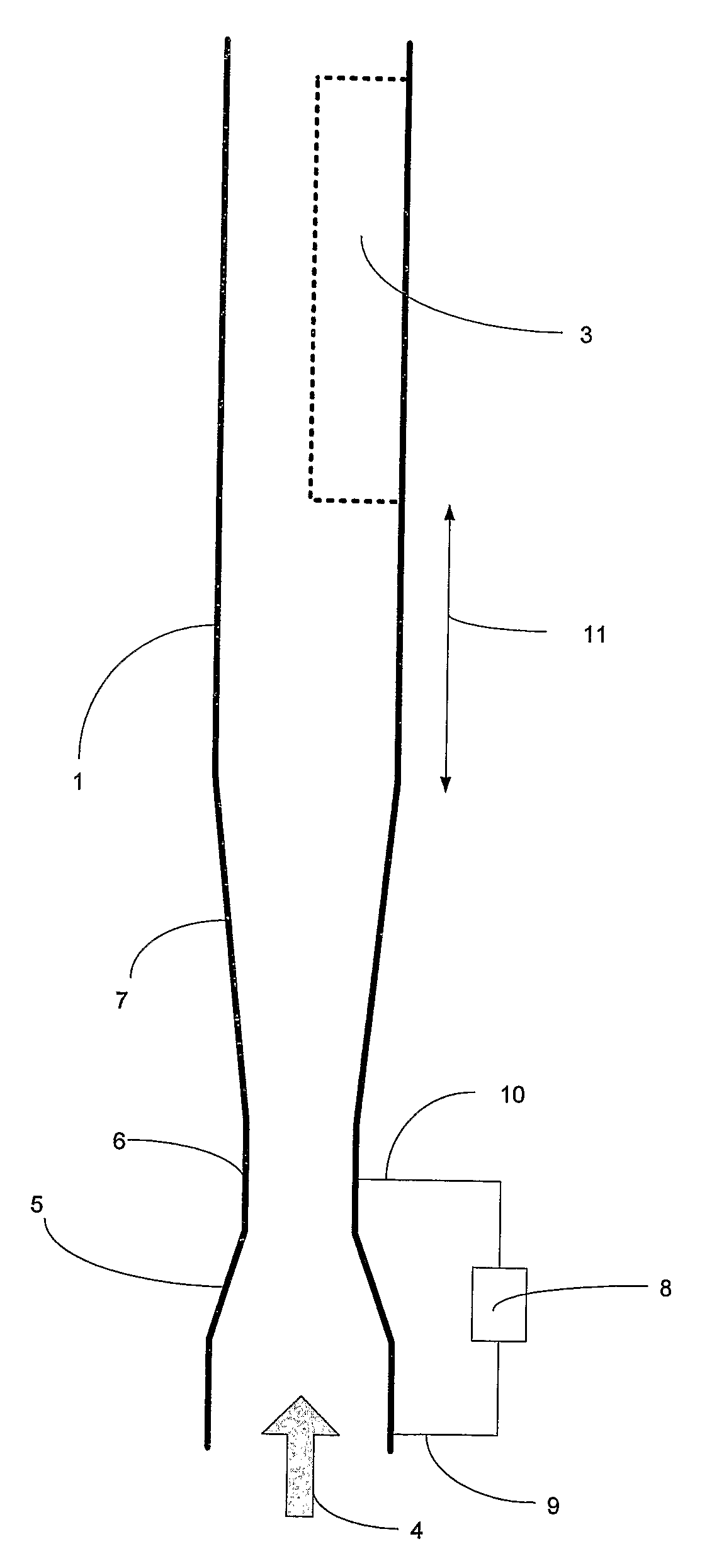
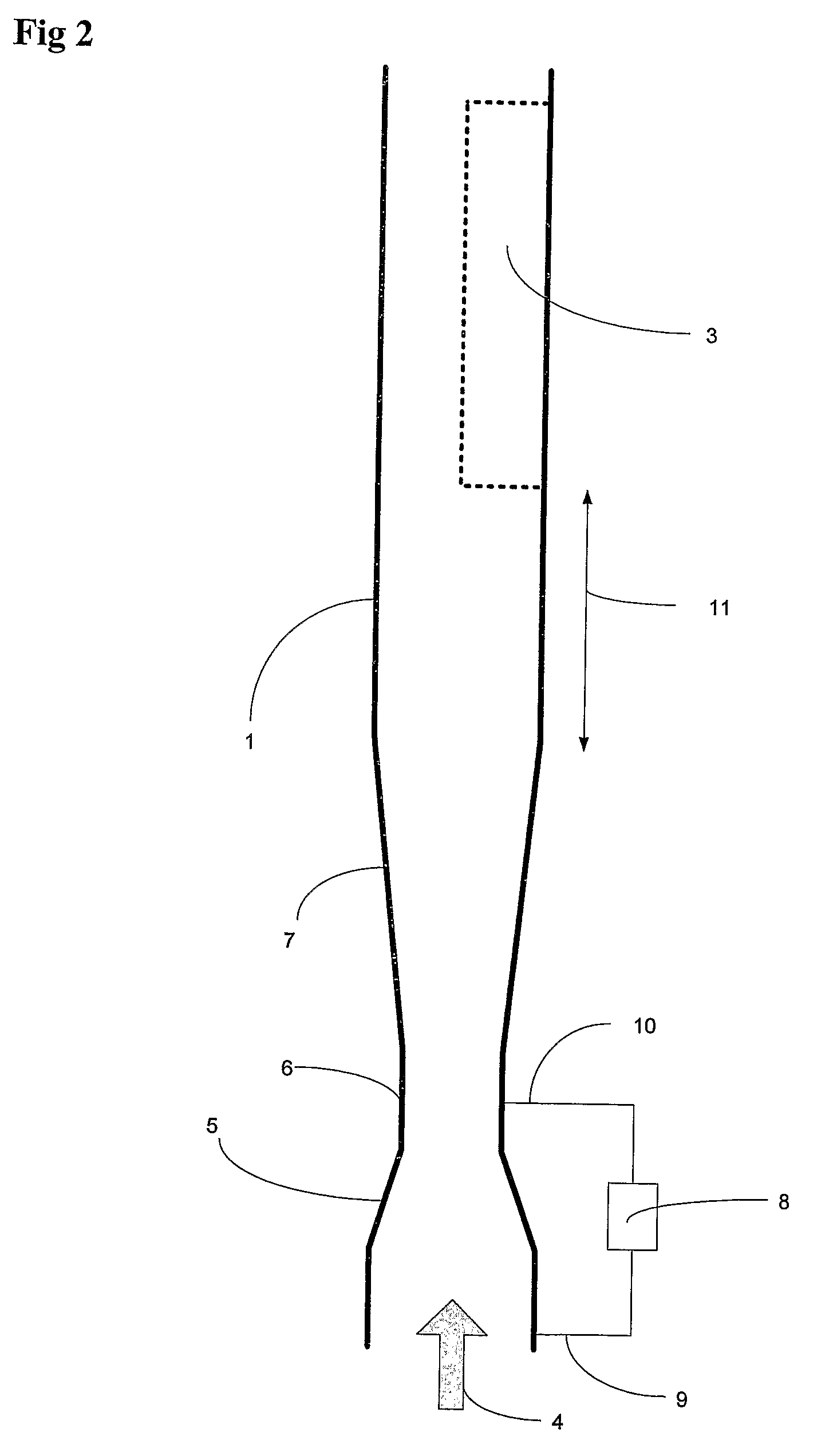
Multiphase meters are normally not mounted in a horizontal position due to the presence of laminar flow, where water is in the bottom of the pipe and gas at the top, which would distort the measurement.
However, when the flow is flowing in vertical pipes, severe concentration of gas in the middle of the pipe has been experienced even at medium flow rates (a few m / s) and gas fractions as low as 10%.
Even a concentration of the gas in the middle of the pipe at lower gas fractions would introduce severe measurement errors.
When a nuclear
densitometer is used to measure the density, it is not possible to obtain
full coverage of the cross section of the pipe.
However, when used in a 6″ pipe, it is difficult to achieve more than 30% coverage of the cross section of the pipe.
However, placing the
nuclear density measurement inside a venturi passage also increases the amount of annular flow in the measurement section.
The error in the measurement will increase as the area of the pipe is increased.
However, the measurement errors due to annular
gas concentration in the middle of the pipe would still be significant.
Annular flow is then minimised; however, the multiphase meter becomes highly intrusive and fragile since it depends on a mechanical restricting or rotating device located in the multiphase
stream.
However, the structure is highly intrusive, thus creating a pressure drop and hence limiting the production capabilities from the wells.
The performance of the mixer would also be dependent on the flow rate and pattern such as length of gas and liquid slugs and could therefore limit the operational envelope of such a multiphase meter.
However, this method is also intrusive and the
repeatability of the measurement over time would also be vulnerable to sand
erosion.
However, all these methods are greatly influenced by annular
gas concentration and would not provide the required measurement accuracy under such conditions.
However all these tomographic techniques require complex sensors and sophisticated measurement algorithms for deriving the composition and flow rates of the multiphase fluid and are therefore difficult to realize in an harsh industrial environment such as pipes with oil, gas and water.
The complexity and rapid changes of multiphase flow combined with the complexity of the measurement algorithms involved in a full-blown tomographic
system may also easily introduce
instability in the calculation routines resulting in large errors in the final calculations.
It is also
time consuming to develop models for such a
system making them difficult to scale for different pipe diameters.
Furthermore, such systems are also
time consuming to configure and calibrate and not well suited for industrial production.
However, the method relies on symmetrical annular gas concentration in the pipe which can not be guaranteed without a conditioning device upstream the multiphase flow meter.
However, none of the devices above are suited for accurate measurements of the flow rates with annular gas concentration in the pipe.
However, if the flow line is straight for a long section, the swirl will diminish.

