Cooling and climate control system and method for a wind turbine

a technology of integrated cooling and climate control system and wind turbine, which is applied in the direction of electric generator control, liquid fuel engine, machines/engines, etc., can solve the problems of noisy fans that force airflow through the radiator, occupy valuable space, and consume power, so as to prevent corrosion, reduce noise, and reduce the effect of nois

Active Publication Date: 2014-06-10
ADWEN OFFSHORE SL
View PDF10 Cites 5 Cited by
  • Summary
  • Abstract
  • Description
  • Claims
  • Application Information

AI Technical Summary

Benefits of technology

[0007]The inventor of the present invention notes that there are various drawbacks to prior art systems. The fans that force the airflow through the radiators are noisy, failure prone, and consume power. Moreover, the radiators occupy valuable space on the nacelle top and could interfere with the helipads that are used for landing helicopters on the nacelle top, for example to transport people to do maintenance. This is especially important in offshore wind turbine installations. Moreover, in an offshore environment, the ambient air has high humidity and carries water droplets and salt particles with it. Therefore, a closed airflow system is more effective in preventing corrosion and electrical short circuits than an open airflow system that is typically used onshore. A closed airflow system necessitates a means to cool the air inside the nacelle.
[0008]The present invention in one embodiment provides an integrated cooling and climate control system that uses the airflow due to the wind to dissipate the heat from the coolant. The system can permit nacelle yawing and does not use air cooled radiators. The system not only helps cool the heat generating components such as the drivetrain, the electrical generator, and the converter, but also helps cool the air inside the nacelle. The airflow can be either closed or open.
[0009]The present invention uses the ambient air as the heat sink. The coolant could be any fluid that is typically used in low temperature heat exchangers, such as a mixture of ethylene glycol and water that does not freeze during the cold weather. The system can not only help cool the heat generating components such as the drivetrain, the electrical generator, and the converter, but can also help cool the air inside the nacelle.

Problems solved by technology

The fans that force the airflow through the radiators are noisy, failure prone, and consume power.
Moreover, the radiators occupy valuable space on the nacelle top and could interfere with the helipads that are used for landing helicopters on the nacelle top, for example to transport people to do maintenance.
Moreover, in an offshore environment, the ambient air has high humidity and carries water droplets and salt particles with it.

Method used


Image

  • Cooling and climate control system and method for a wind turbine
  • Cooling and climate control system and method for a wind turbine
  • Cooling and climate control system and method for a wind turbine

Examples


first embodiment

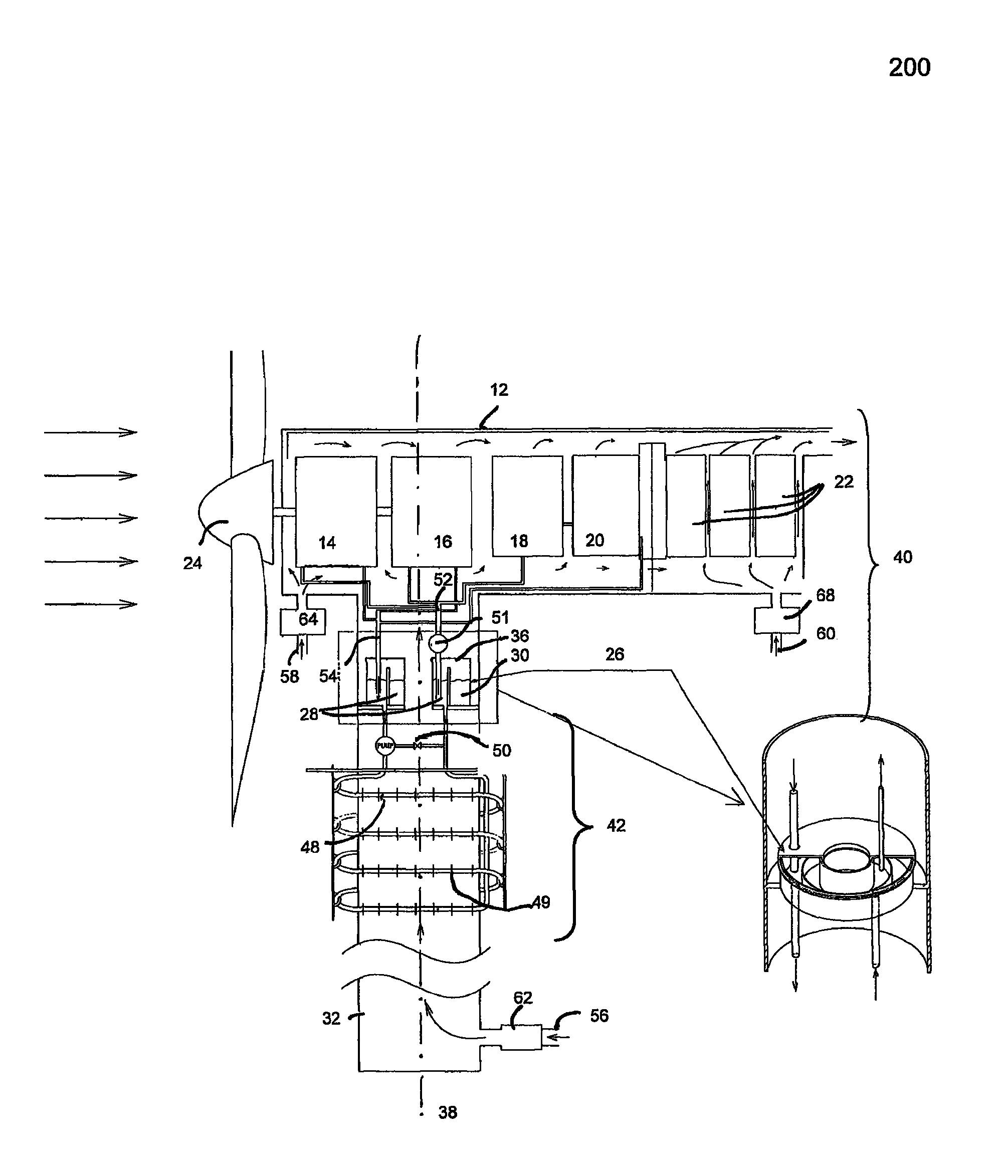
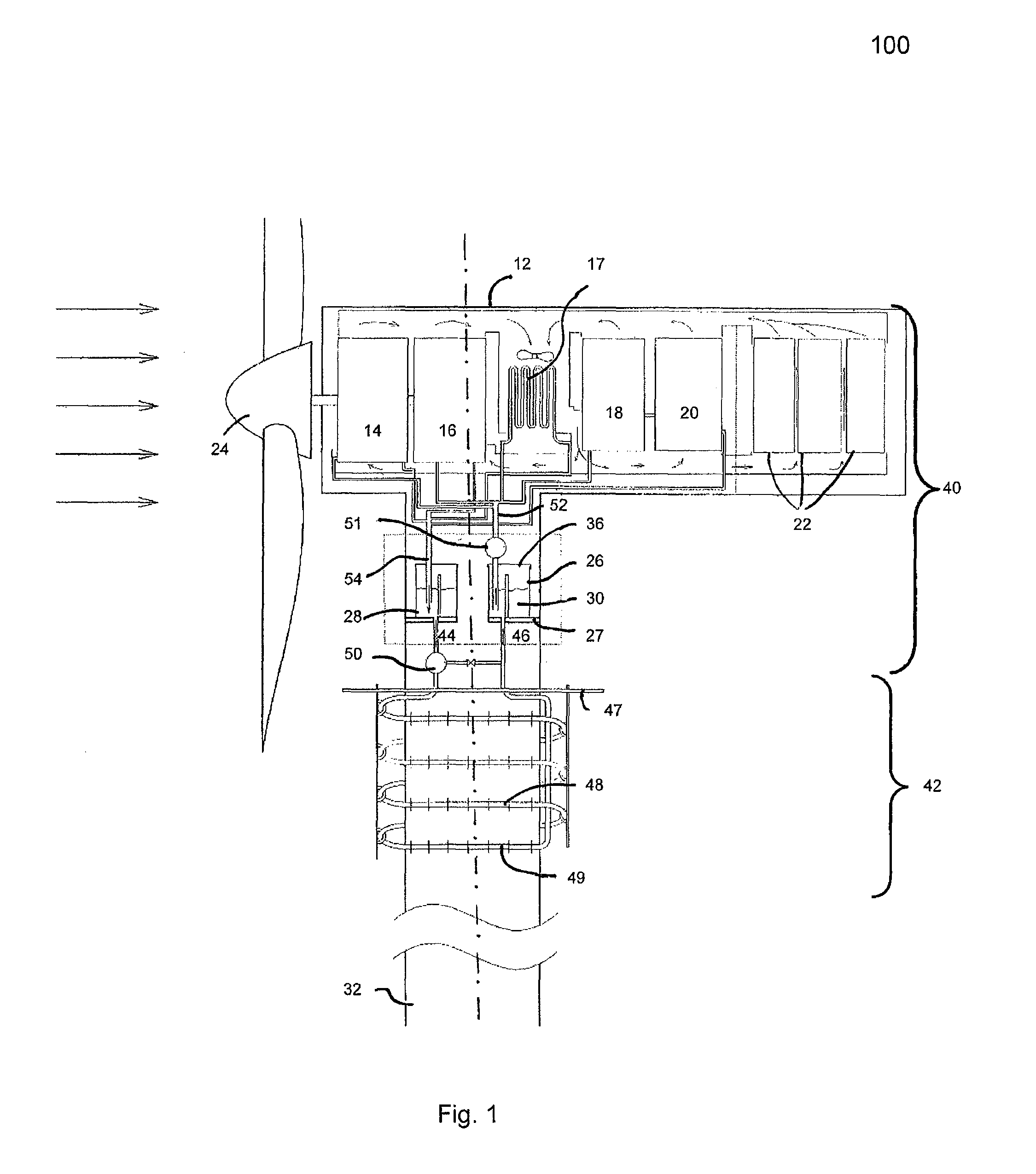
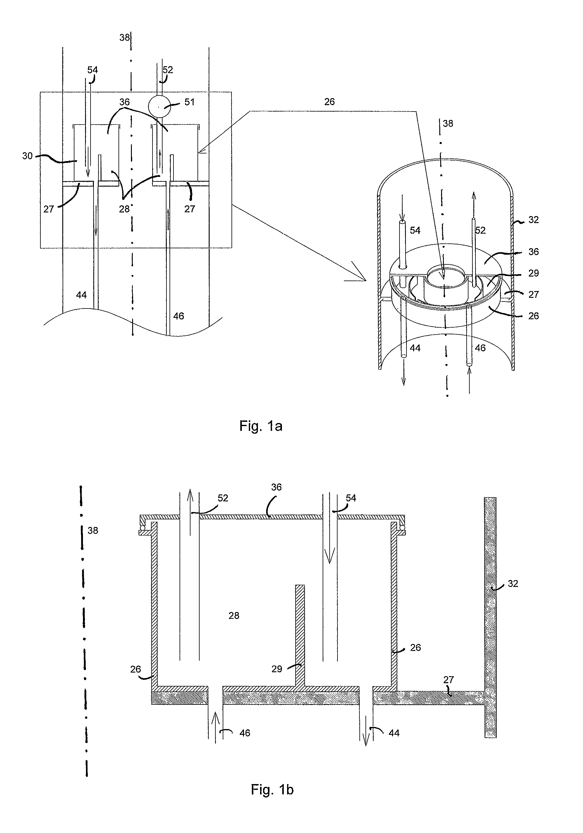
[0026]FIG. 1 shows the cooling and climate control system 100 for a wind turbine according to the present invention. FIGS. 1a and 1b show close-up views of parts of FIG. 1. The system 100 has a nacelle 12 that houses the heat generating components, including the drivetrain (or gear box) 14, the generator 16, the coolant-to-air heat exchanger 17, the hydraulics unit 18, the converter 20, and the transformer 22. On its top, the turbine tower 32 supports the nacelle 12 and the rotor 24.

[0027]One notable feature of this system 100 is a cylindrical reservoir 26 that rests on a platform 27 inside the tower 32 just below the lower part of the nacelle 12. The reservoir 26 is hollow in the center and has multiple pairs of annular chambers. In the basic case, the reservoir 26 has only one pair of chambers 28 and 30 and contains only the coolant. The two chambers 28 and 30 are separated by a circular wall 29 in the middle. The height of the dividing wall 29 in the middle is lower than the inne...

third embodiment

[0036]Thus, FIGS. 3 and 3a show the cooling and climate control system for a wind turbine where the coolant, the lubricating oil, and the hydraulic fluid independently and directly dissipate the heat to the ambient air. In this system, the annular cylindrical reservoir 26 has a separate pair of annular fluid chambers (28a and 30a, 28b and 30b, and 28c and 30c, for the coolant, the lubricating oil and the hydraulic fluid, respectively), a flow pump (in the upper cooling circuit) (not shown) (similar to 51 in FIG. 1 for each of the three fluid circuits), and respective cooling coils 48a, 48b and 48c (for the coolant, the lubricating oil, and the hydraulic fluid, respectively) on the outside of the tower 32 for each of the fluids (coolant, lubricating oil, and hydraulic fluid) that help cool the heat generating components in the nacelle 12. The pairs of these chambers (28a and 30a, 28b and 30b, and 28c and 30c) are fully separated from one another to prevent mixing of fluids. As descri...


PUM


Abstract

A system to cool the air inside a nacelle of a wind turbine. The system has an upper cooling circuit, with a reservoir disposed below the nacelle. The reservoir has at least one pair of annular chambers and a lid that freely rotates about its axis and about the nacelle yaw axis. Coolant flows from a first annular chamber to a second annular chamber through a heat exchanger in the nacelle, thereby carrying heat from the nacelle to the second annular chamber. The system also has a lower cooling circuit, having a coil that connects the first annular chamber to the second annular chamber and being exposed to the outside of the wind turbine. Coolant flows from the second annular chamber to the first annular chamber through the coil, thereby dissipating the heat to ambient air.

Description

BACKGROUND OF THE INVENTION[0001]1. Field of the Invention[0002]The present invention generally relates to an integrated cooling and climate control system and method for a wind turbine, and more particularly to systems and methods to cool the air inside the nacelle and the heat generating components of a wind turbine such as the drivetrain, the electrical generator, the converter, and the transformer.[0003]2. Related Art[0004]A wind turbine converts the kinetic energy of wind into electrical energy through its rotor, drivetrain, electrical generator, and converter. An electrical transformer converts the low voltage output from the converter into a high voltage output before the output is sent to the substation at the wind farm. The wind turbine nacelle houses these mechanical and electrical components, namely, the drivetrain, the electrical generator, the converter, and the transformer (usually located in the nacelle to reduce the power loss due to low voltage electrical transmissi...

Claims


Application Information

Patent Timeline
Patent Type & Authority Patents(United States)
IPC IPC(8): F03D11/00
CPCY02T50/675F05B2260/205F03D11/0075Y02E10/726F05B2260/20Y02E10/722F03D80/60F03D80/88Y02E10/72Y02T50/60
Inventor SABHAPATHY, PERI
Owner ADWEN OFFSHORE SL
Why Eureka
Try Eureka