
Monitoring device, method and system

a monitoring device and vital sign technology, applied in the field of real-time vital sign monitoring devices, can solve the problems of prior art devices suffering from noise, light and motion related problems, and prone to artifacts, and achieve the effect of light weigh

Inactive Publication Date: 2009-12-01
IMPACT SPORTS TECH
View PDF6 Cites 73 Cited by
  • Summary
  • Abstract
  • Description
  • Claims
  • Application Information

AI Technical Summary

Benefits of technology

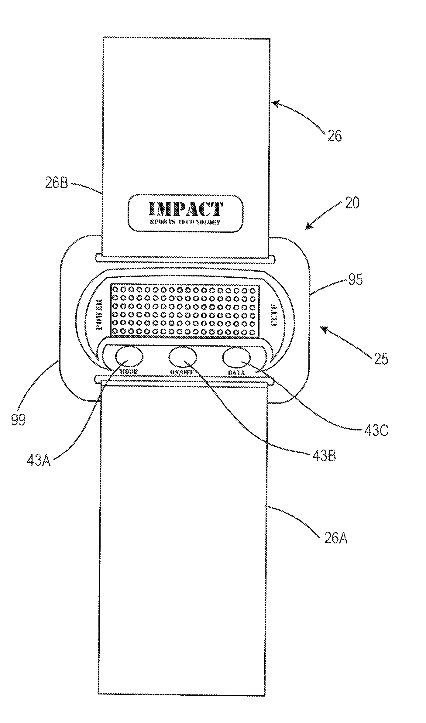
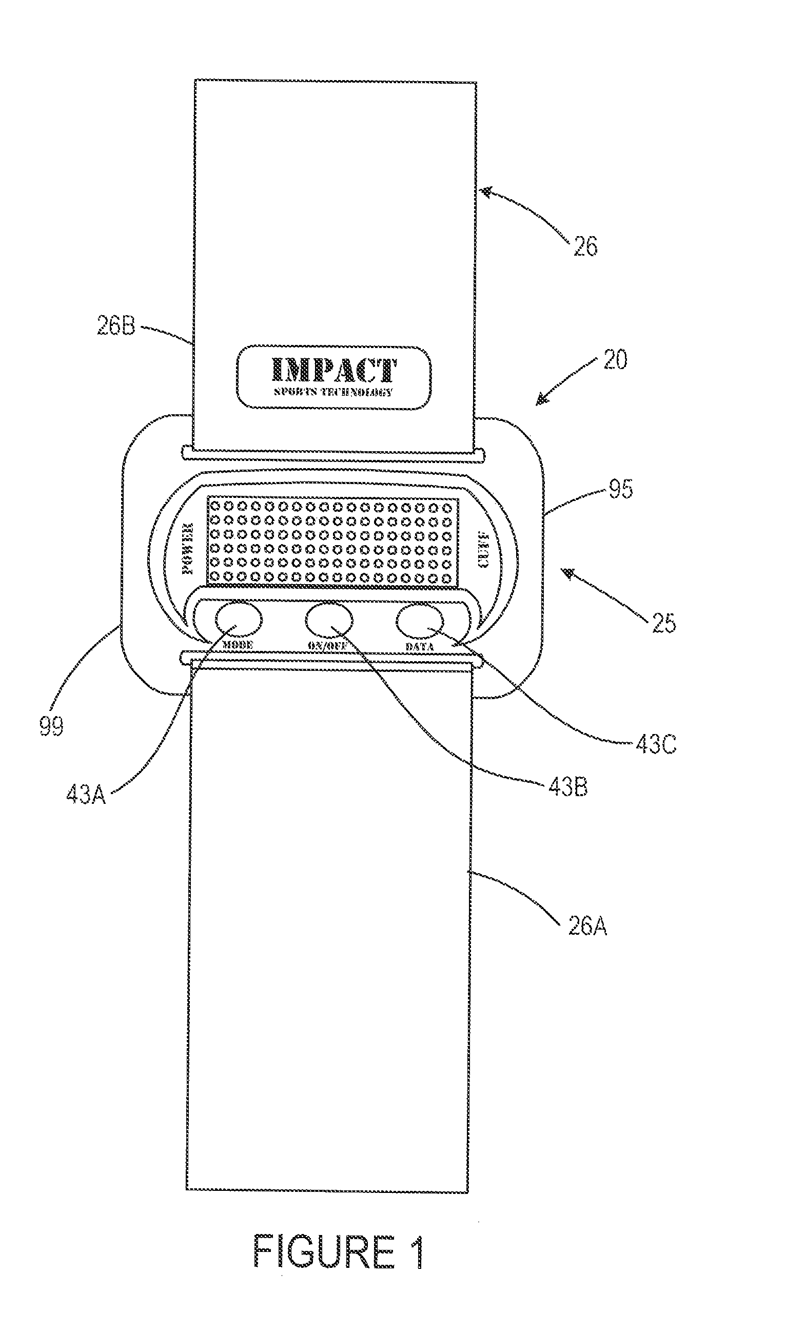
"The present invention provides a solution for accurately monitoring a user's vital signs for extended periods of time. The monitoring device is comfortable to wear, allows for input and controlled output, is light weight, and provides sufficient real-time information to the user about their health. The monitoring device includes an optical sensor, a circuitry assembly, a display member, and a control component. The monitoring device can be attached to the user's wrist, arm, or ankle. The control component controls the input and output of information displayed on the display member. The invention has applications in real-time monitoring of a user's vital signs during a live event within a playing environment."

Problems solved by technology

The disadvantages of pulse oximetry devices are that it is prone to artifact, it is inaccurate at saturation levels below 70%, and there is a minimal risk of burns in poor perfusion states.
Several factors can cause inaccurate readings using pulse oximetry including ambient light, deep skin pigment, excessive motion, fingernail polish, low flow caused by cardiac bypass, hypotension, vasoconstriction, and the like.
However, the prior art devices often suffer from noise, light and motion related problems.
These problems are increased when the user participates in an athletic activity such as running.
Further, attempting to correct one problem often creates additional problems such as increasing a sensor output which results in a shorter battery life.
The prior art has failed to provide a means for monitoring one's health that is accurate, easy to wear on one's body for extended time periods, allows the user to input information and control the output, and provides sufficient information to the user about the user's health.

Method used


Image

  • Monitoring device, method and system
  • Monitoring device, method and system
  • Monitoring device, method and system

Examples


example one

[0090]Female, 30 yrs old, height 167.6 centimeters, weight 54.5 kilograms.

[0091]The BMR=655+523+302−141=1339 calories / day.

[0092]The BMR is 1339 calories per day. The activity level is moderately active (work out 3-4 times per week). The activity factor is 1.55. The TDEE=1.55×1339=2075 calories / day. TDEE is calculated by multiplying the BMR of the user by the activity multiplier of the user.

[0093]The heart rate may be used to dynamically determine an activity level and periodically recalculate the calories burned based upon that factor. An example of such an activity level look up table might be as follows:

[0094]Activity / Intensity Multiplier Based on Heart Rate

Sedentary=BMR×1.2(little or no exercise, average heart rate 65-75bpm or lower)

Lightly active=BMR×3.5(light exercise, 75bpm-115bpm)

Mod. active=BMR×5.75(moderate exercise, 115-140pm)

Very active=BMR×9.25(hard exercise, 140-175bpm)

Extra active=BMR×13(175 bpm−maximum heart rate as calculated with MHR formula)

[0095]For example, while...


PUM


Abstract

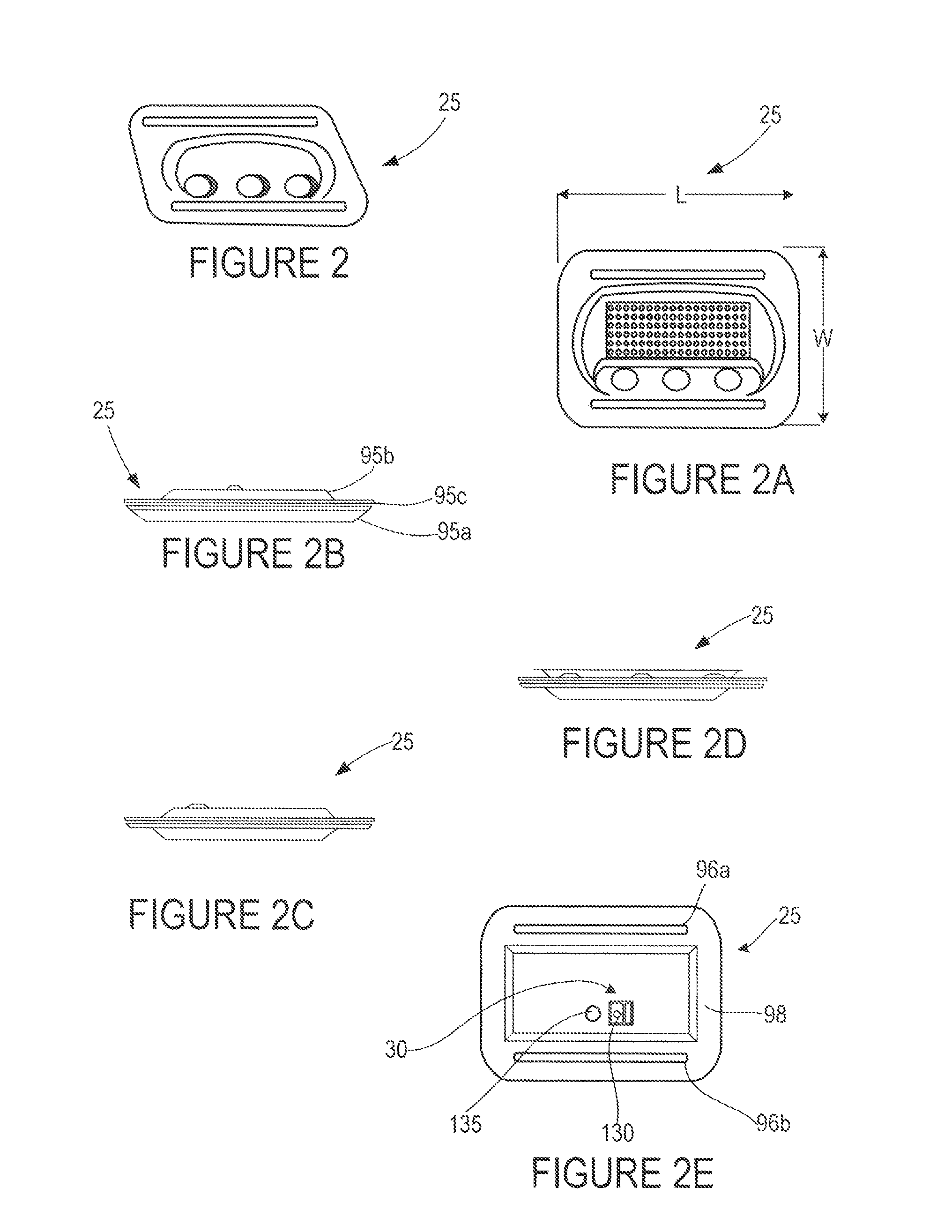
A monitoring device (20) for monitoring the vital signs of a user is disclosed herein. The monitoring device (20) is preferably an article (25) having an optical sensor (30) and a circuitry assembly (35). The optical sensor (30) preferably comprises a photodetector (130) and a plurality of light emitting diodes (135). The monitoring device (20) preferably provides for the display of the following information about the user: pulse rate; blood oxygenation levels; calories expended by the user of a pre-set time period; target zones of activity; time; or distance traveled.

Description

CROSS REFERENCES TO RELATED APPLICATIONS[0001]The Present application is a continuation application of U.S. patent application Ser. No. 11 / 762,078, filed on Jun. 13, 2007, now U.S. Pat. No. 7,468,036.STATEMENT REGARDING FEDERALLY SPONSORED RESEARCH OR DEVELOPMENT[0002]Not ApplicableBACKGROUND OF THE INVENTION[0003]1. Field of the Invention[0004]The present invention is related to real-time vital sign monitoring devices. More specifically, the present invention relates to a device for monitoring a user's vital signs.[0005]2. Description of the Related Art[0006]There is a need to know how one is doing from a health perspective. In some individuals, there is a daily, even hourly, need to know one's health. The prior art has provided some devices to meet this need.[0007]One such device is a pulse oximetry device. Pulse oximetry is used to determine the oxygen saturation of arterial blood. Pulse oximeter devices typically contain two light emitting diodes: one in the red band of light (6...

Claims


Application Information

Patent Timeline
Patent Type & Authority Patents(United States)
IPC IPC(8): A61B5/00
CPCA61B5/02055A61B5/681A61B5/222A61B5/14552A61B5/11
Inventor BRADY, DONALDHUNT, MARKELHAG, SAMMY I.RULKOV, NIKOLAILUI, STEVE
Owner IMPACT SPORTS TECH
Learn More