Automatic frequency compensation for pulse width modulated RF level control

a pulse width modulation and level control technology, applied in pulse automatic control, power conversion systems, instruments, etc., can solve the problems of cost, complexity, and generally requires twice the silicon, and achieve different challenges

Inactive Publication Date: 2009-12-01
AMBRELL CORP
View PDF10 Cites 38 Cited by
  • Summary
  • Abstract
  • Description
  • Claims
  • Application Information

AI Technical Summary

Problems solved by technology

Disadvantages of this method are that it is costly, complex and generally requires twice the silicon (in power semiconductors) than is required by a direct off-line architecture.
Varying (controlling) the RF power level using a direct off-line architecture is less costly, however this approach presents a different set of challenges to the designer.

Method used


Image

  • Automatic frequency compensation for pulse width modulated RF level control
  • Automatic frequency compensation for pulse width modulated RF level control
  • Automatic frequency compensation for pulse width modulated RF level control

Examples


Embodiment Construction

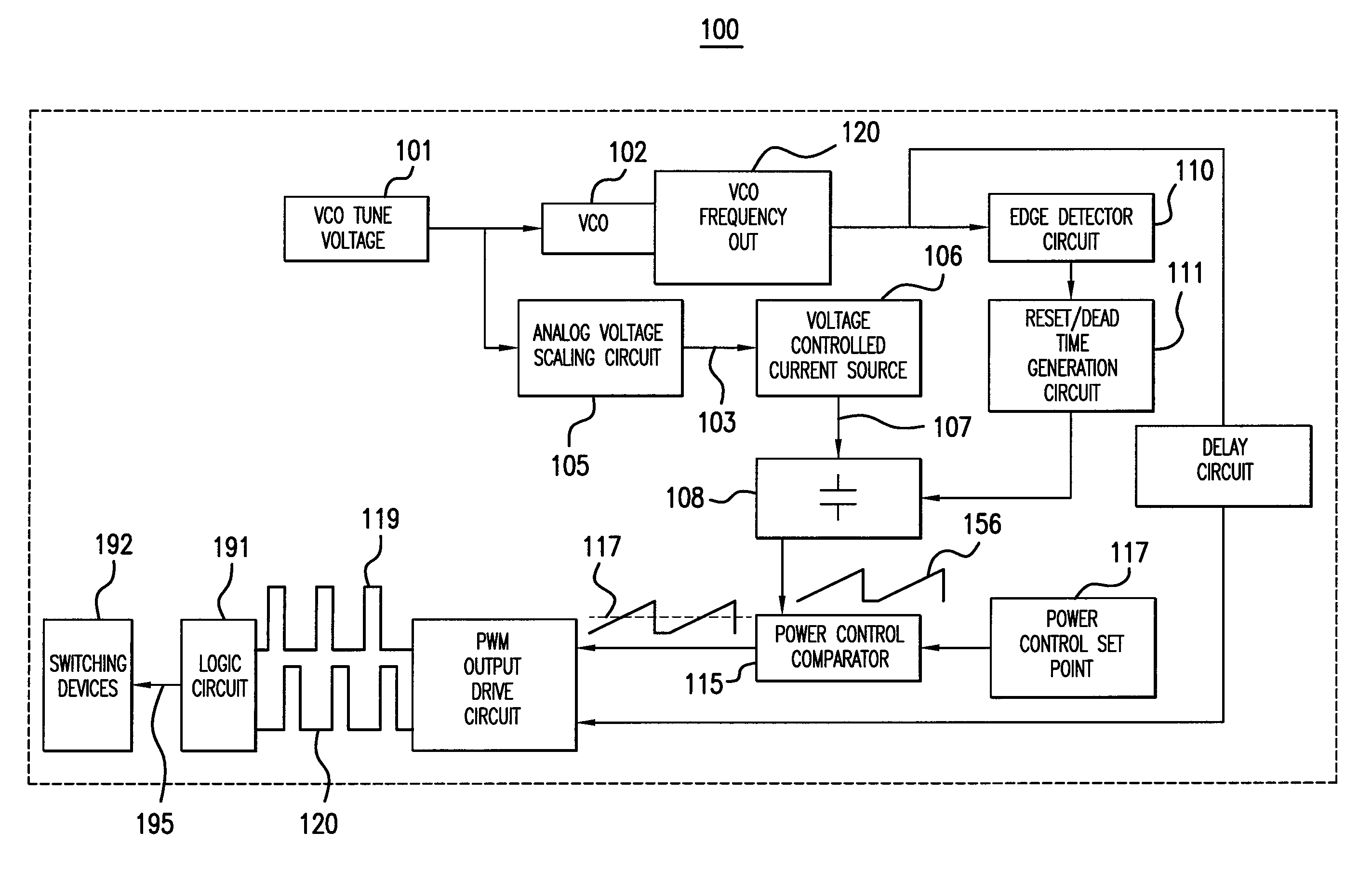
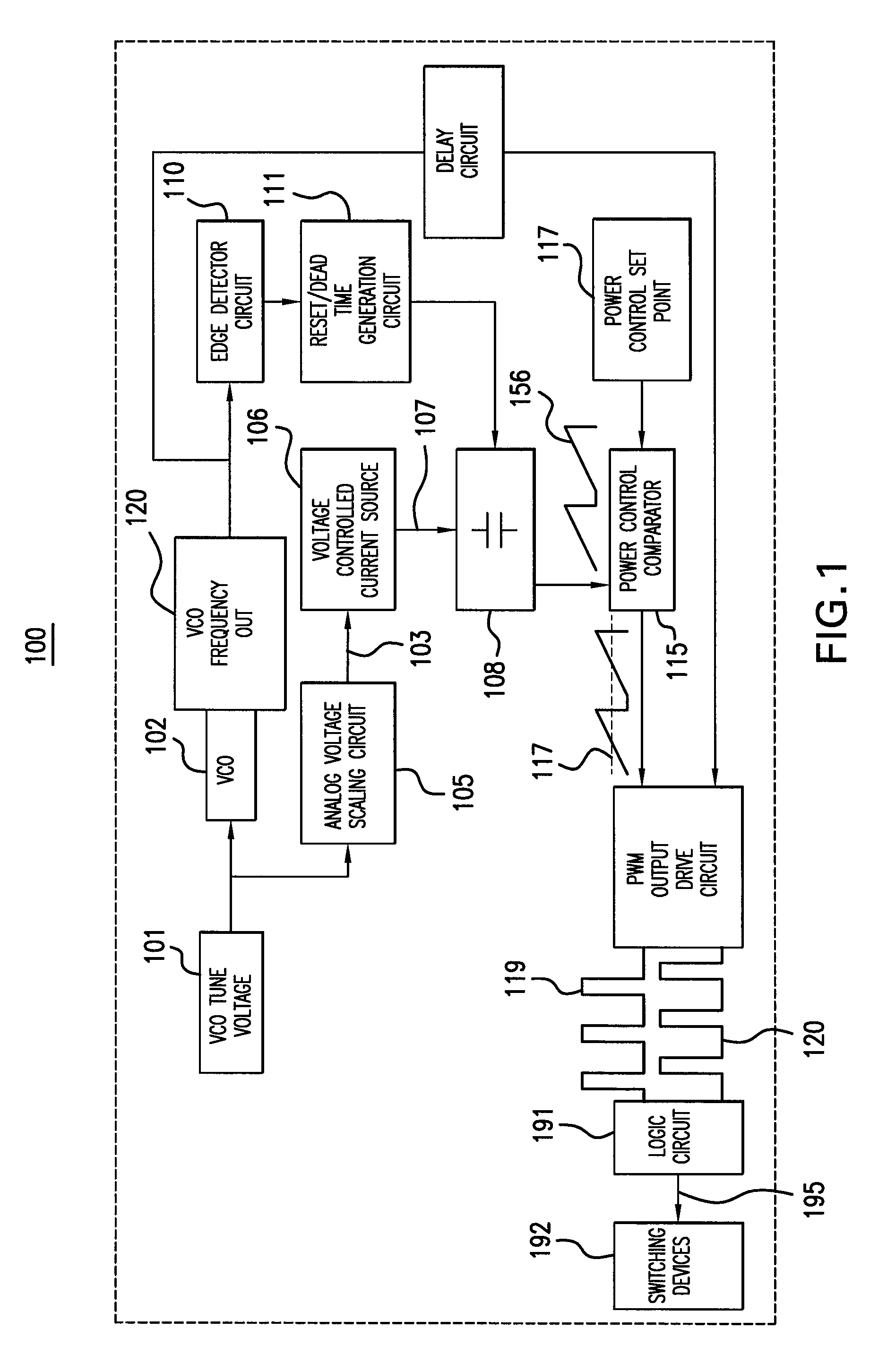
[0020]FIG. 1 illustrates a system 100 according to an embodiment of the invention. System 100 automatically allocates to switching devices (e.g., power transistors) 192 an on-time that is proportional to the cycle time.

[0021]According to an embodiment of the present invention, resonant frequency is constantly adjusted for in a closed loop that employs a voltage controlled oscillator (VCO) 102 that produces a drive signal 120. A VCO tune voltage 101, which is received by VCO 102 and controls the frequency of the drive signal 120 outputted by VCO 102, is linearly proportional to operating (resonant) frequency. This tune voltage 101 is received by and used to control a current source 106 that charges a circuit 108 that accumulates charge. Circuit 108, in preferred embodiments is a capacitor or includes one or more capacitors. Without limiting the invention, circuit 108 shall be referred to herein as “capacitor 108.” As illustrated in FIG. 1, tune voltage 101 may be processed by an anal...


PUM


Abstract

Preferred embodiments of the present invention provide systems and methods that automatically correct the desired on-time of switching elements as the resonant frequency changes, so as to maintain the correct proportional value.

Description

BACKGROUND OF THE INVENTION[0001]1. Field of the invention[0002]The present invention relates to systems and methods for controlling RF output power.[0003]2. Discussion of the Background[0004]To address a variety of applications, RF power supplies (e.g., RF power supplies used in Induction heating) must employ a method of varying RF output power. There are many ways to accomplish this. Some architectures simply supply a variable DC source to the RF output power stage of the power supply. The result has the advantage of a continuous (rather than discontinuous) RF output with a variable and easily measurable amplitude whose heating effects and harmonics are predictable. Disadvantages of this method are that it is costly, complex and generally requires twice the silicon (in power semiconductors) than is required by a direct off-line architecture.[0005]Varying (controlling) the RF power level using a direct off-line architecture is less costly, however this approach presents a different...

Claims


Application Information

Patent Timeline
Patent Type & Authority Patents(United States)
IPC IPC(8): H03L7/00G05F1/00
CPCH05B6/06H03K7/08
Inventor PAULL, IAN ALAN
Owner AMBRELL CORP
Why Eureka
Try Eureka