Girder system employing bent steel plating

a technology of bent steel and girders, which is applied in the direction of bridges, other domestic objects, load-supporting pillars, etc., can solve the problems of long delay, increase the cost, maintenance cost and labor of bridge installation, and relatively expensive finished products, so as to increase the buckling capacity of the girder, good structural stability, and relative simplicity in fabrication

Active Publication Date: 2009-12-08
NUTECH VENTURES
View PDF21 Cites 8 Cited by
  • Summary
  • Abstract
  • Description
  • Claims
  • Application Information

AI Technical Summary

Benefits of technology

[0006]A structural support system is provided utilizing bent steel plate girders. The girders employ a modified inverted box cross-sectional configuration to provide a longitudinal load-carrying member with good structural stability and relative simplicity in fabrication. In one aspect, the girder is formed with an upper flange section, a set of web sections extending from opposite lateral sides of the upper flange section, and a base section below the web sections. The upper flange section may be formed with a longitudinal ridge to increase the buckling capacity of the girder, as well as provide a feature for physically coupling the girder with an overlying superstructure, such as a bridge deck, to form the structural support system. A set of upper transitional bends form the interface between the upper flange section and the web sections. The base section includes individual flanged footings that project generally towards one another.
[0009]As described, the structural support system possessing a modified inverted box cross-sectional configuration, and method of assembly therefore, provide a rapidly deployable load-carrying system with a reduced number of fabrication steps as compared to conventional methods. Particularly in the case of the girder formed entirely by bending processes, an individual girder pattern may be selected and quickly duplicated to generate a series of matching girders for a given bridge span or other structural support system design. Structural support systems of the present invention may be formed by joining a series of girders with an overlying deck at an installation site, or may be deployed to an installation site as a preassembled deck / girder unit.

Problems solved by technology

Despite advances in design for load carrying systems, conventional fabrication methods for steel girders are still generally labor intensive, and result in a finished product that is relatively expensive.
Furthermore, because of the extent of welding that is necessary, there is frequently a long delay introduced from the time a particular girder design is chosen to the time a load carrying system is constructed on-site.
These cross frames add to the expense, maintenance cost and labor of bridge installation.

Method used


Image

  • Girder system employing bent steel plating
  • Girder system employing bent steel plating
  • Girder system employing bent steel plating

Examples


Embodiment Construction

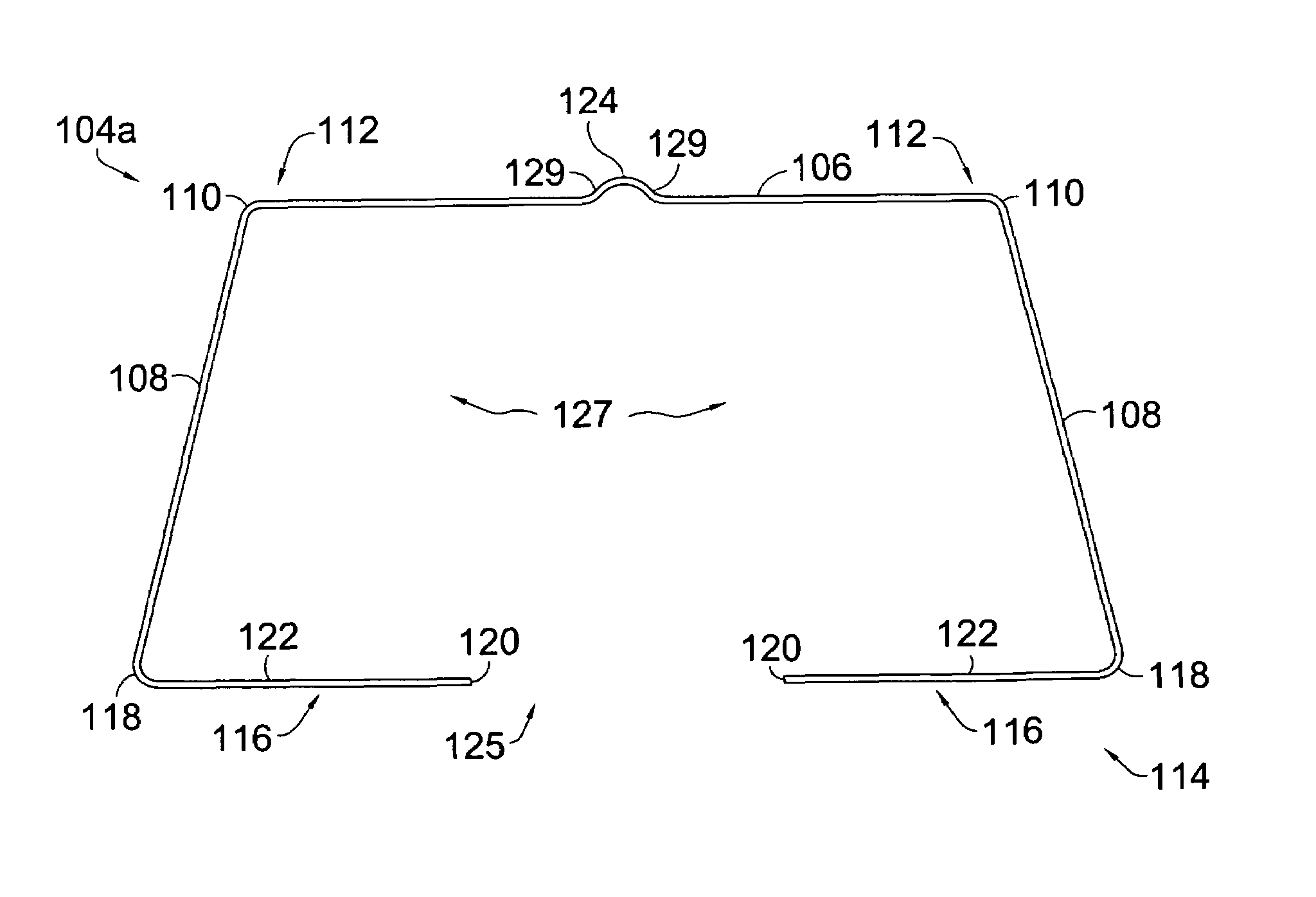
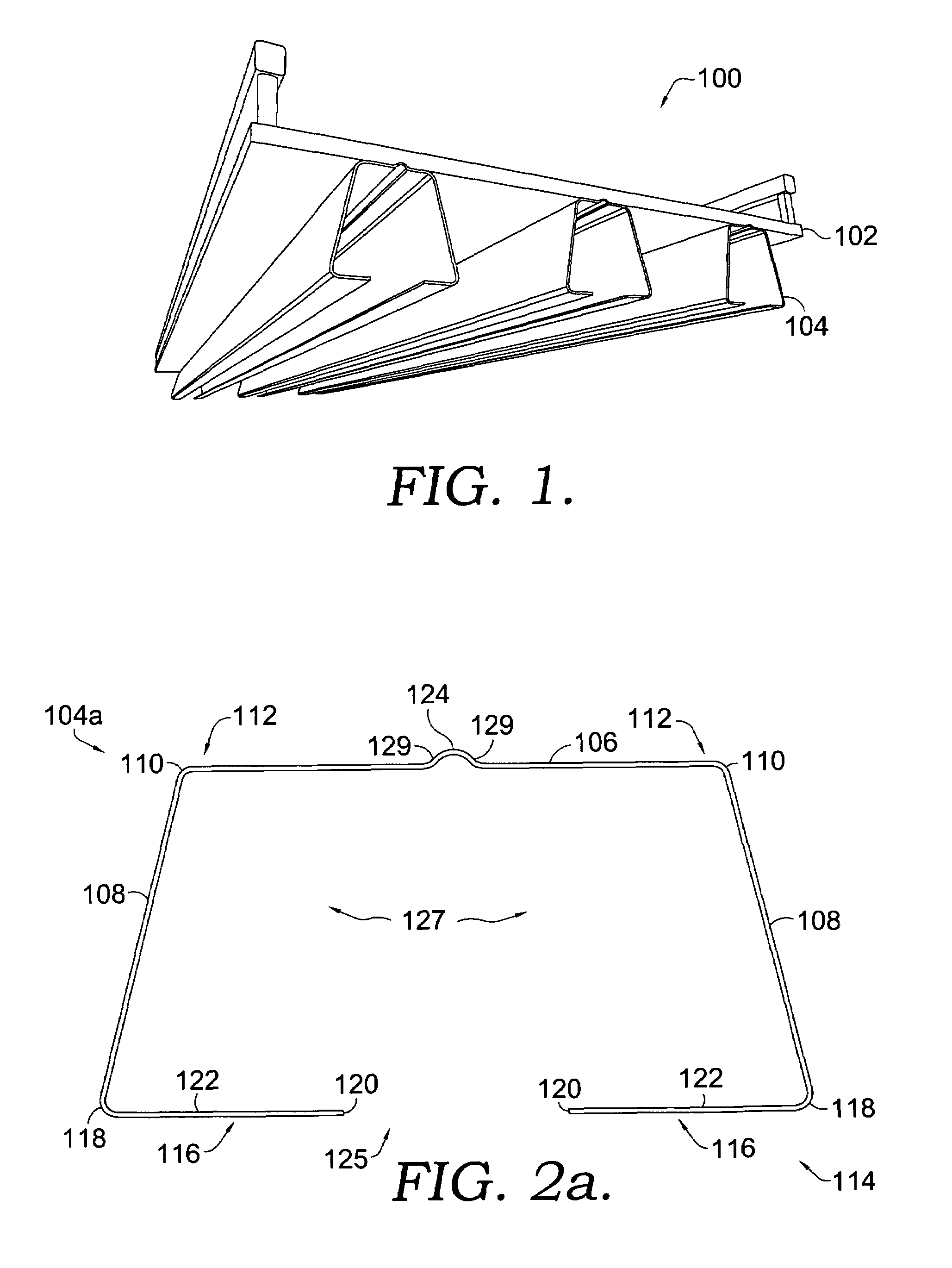
[0016]Turning now to the drawings, and initially to FIG. 1, a structural support system 100 is depicted for providing a load-carrying element. The system 100 is particularly well suited for supporting loads upon a deck 102 supported by a series of underlying girders 104 that extend generally in a horizontal longitudinal orientation, such as in the form of a bridge span or building floor span. It should be understood, however, that the orientation of the deck 102 and underlying girders 104 may vary from the horizontal, such as in the case of a bridge span having a convex or concave longitudinal profile with respect to the horizontal plane, or ascending or descending in elevation longitudinally over the span. Additionally, descriptions of deck 102 or girder 104 components or features as being “upper” or “lower”, and orientations or interrelations of such components or features described as “upwardly”, “downwardly”, “underlying” or “overlying”, are with reference to the deck 102 and gi...


PUM

PropertyMeasurementUnit
thicknessaaaaaaaaaa
thicknessaaaaaaaaaa
strength-aaaaaaaaaa

Abstract

A structural support system employs a modified inverted box girder design for improved performance and ease of fabrication. Each girder of a series of girders is formed with an upper flange section, a set of web sections extending from opposite lateral sides of the upper flange section, and a base section below the web sections. The base section includes individual flanged footings that project generally towards one another. The particular cross-sectional configuration of each girder may be formed by bending a continuous steel plate along at least a first set of preselected parallel lines to establish a set of upper continuous transitional bends with the upper flange section therebetween, as well as a remainder portion forming at least the set of web sections. A deck is coupled with the series of girders to form the structural support system.

Description

CROSS-REFERENCE TO RELATED APPLICATIONS[0001]This application claims priority to commonly owned U.S. provisional application Ser. No. 60 / 671,736, filed Apr. 15, 2005, incorporated by reference in its entirety.STATEMENT REGARDING FEDERALLY SPONSORED RESEARCH OR DEVELOPMENT[0002]Not applicable.BACKGROUND OF THE INVENTION[0003]Structural support systems, such as those used in buildings or bridges, often incorporate steel girders to form a load-carrying element. For instance, in the case of bridges, the generally horizontally extending girders provide support to an overlying superstructure (e.g., a bridge deck) and transfer loads to support columns or other structures anchored to the ground. Girders have a variety of cross-sectional configurations, such as I-beam and box-shaped, each providing specific advantages depending on the particular design parameters for a load carrying system. In certain situations, for example, it is desirable to maximize the strength-to-weight ratio for a gir...

Claims


Application Information

Patent Timeline
Patent Type & Authority Patents(United States)
IPC IPC(8): E01D2/04
CPCE01D2/00Y10T29/49634E01D2101/268
Inventor AZIZINAMINI, ATOROD
Owner NUTECH VENTURES
Why Eureka
Try Eureka