Ultrasonic strain imaging device and method providing parallel displacement processing

a technology of strain imaging and parallel displacement processing, applied in the field of ultrasonic imaging, can solve the problems of limiting the necessary area of the search window, reducing the chance of possible false matches, and managing the computational burden of matching points with each other

Active Publication Date: 2009-12-15
WISCONSIN ALUMNI RES FOUND
View PDF7 Cites 3 Cited by
  • Summary
  • Abstract
  • Description
  • Claims
  • Application Information

AI Technical Summary

Benefits of technology

[0015]The present inventors have recognized that parallel processing can be practical in elasticity imaging by the simple expedient of computing displacements along columns of tissue rather than on a row-by-row basis. Note that a column is defined as a data segment generally parallel to the axis of the ultrasonic beam. The early calculations necessary for each column remain near the transducer allowing efficient search windows to be used, and previous column data allows continued refinement of the window sizes and locations as with the row-by-row approach. The computation of displacement data in two columns progressing outward from a pre-computed center column substantially eliminates the problem of collisions. Additional time taken in the determination of displacement for the central column, which need be done only once, benefits the remaining column calculations.
[0021]Thus it is an object of at least one embodiment of the invention to employ a computational sequence that eliminates collisions between computations of independent columns.
[0023]It is thus another object of at least one embodiment of the invention to acquire data in a location that induces less undesirable motion (i.e. lateral and out-of-plane motion) and that is beneficial for balancing loads among two computing processors.
[0024]The determination of displacement of elements in the first column may use more complex processing, for example, by comparing data points in the first and second ultrasound echo data sampled at different frequencies from coarse to fine for more robust estimates. Statistical methods requiring more computing time (e.g. Viterbi algorithm (IEEE Trans. Information Theory, 1967) based on the Hidden Markov Model (Grimmett and Stirzaker, “Probability and random processes”, 2nd ed., Oxford University Press, 1992) may also be used in determining displacement elements in the first column for more robust estimates.
[0025]Thus it is an object of at least one embodiment of the invention to effectively allocate additional computational resources to the first column estimation that may have the greatest interest.
[0031]It is thus another object of at least one embodiment of the invention to provide improved robustness to a first guiding column by looking at spatially independent columns of data.

Problems solved by technology

Normally the size of the search window must be great enough to accommodate likely tissue displacements between the pre-deformation and post-deformation images, but limited to manage the computational burden of matching points with each other and to reduce the chance of possible false matches that violate a priori assumptions about limited mobility of a continuum reacting to external mechanical stimuli.
The computation of displacements starts at a row closest to the transducer and having lowest expected displacements, thereby limiting the necessary area of the search windows.
Unfortunately, each successive row of displacement data is highly dependent on the earlier rows, particularly for refining the size and location of the search windows.
Further, independent processing of the rows in small groups associated with different processors raises a problem of “collisions” in which errors in the calculations of individual rows are propagated within the group to produce discontinuities when the groups meet at interfaces between the groups.

Method used


Image

  • Ultrasonic strain imaging device and method providing parallel displacement processing
  • Ultrasonic strain imaging device and method providing parallel displacement processing
  • Ultrasonic strain imaging device and method providing parallel displacement processing

Examples


Embodiment Construction

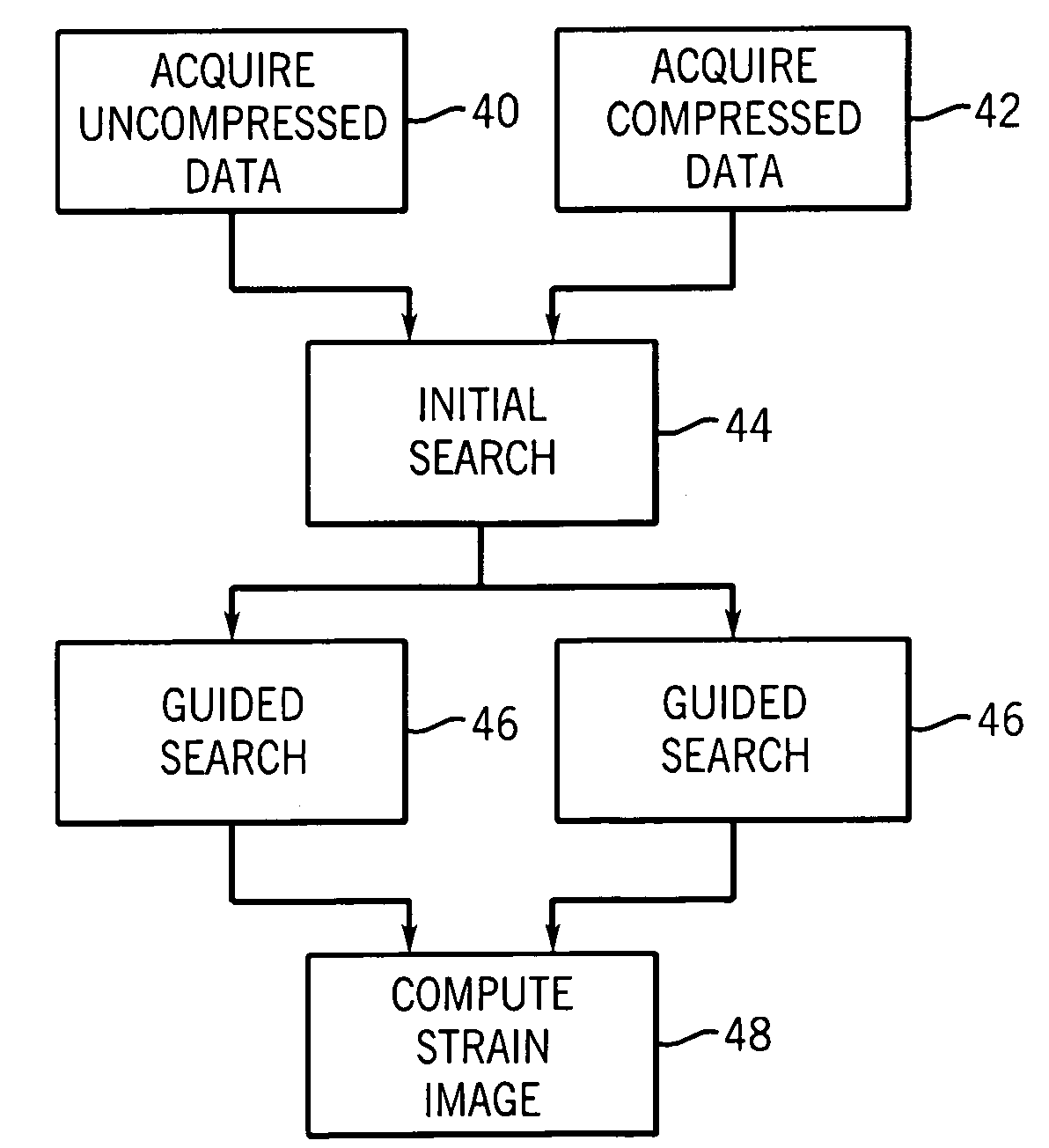
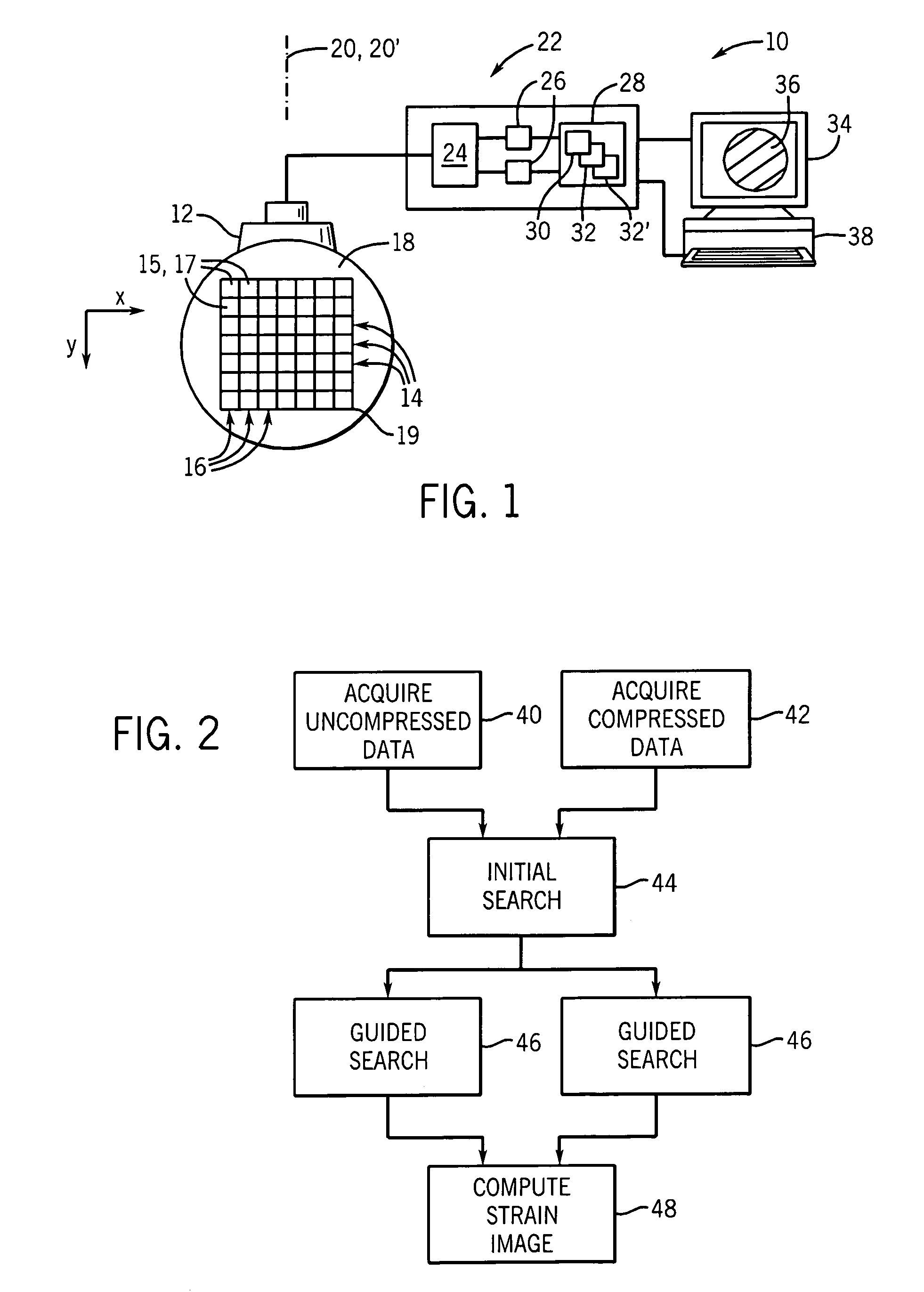
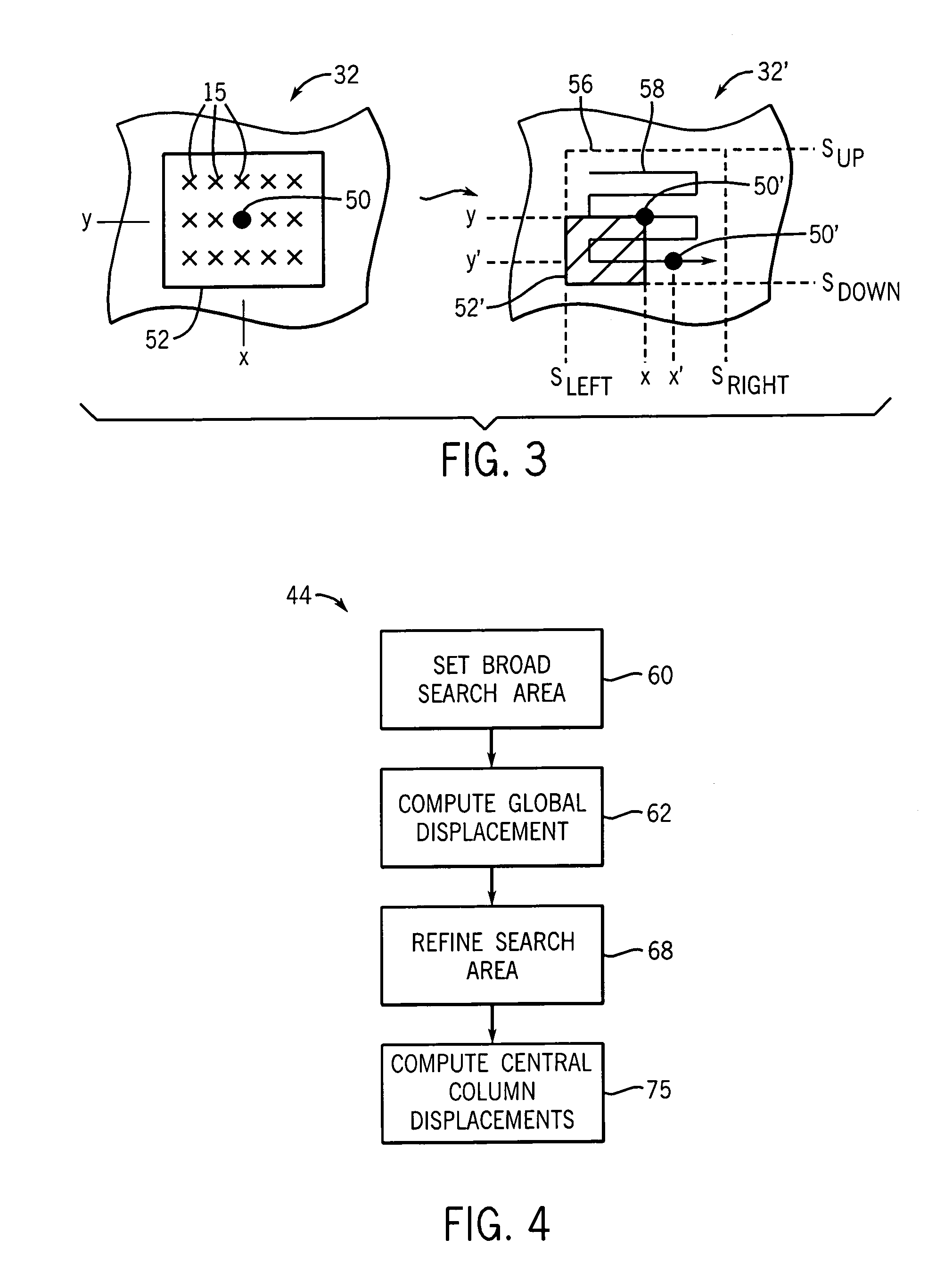
[0051]Referring now to FIG. 1, an elasticity imaging machine 10 of the present invention includes an ultrasonic array transducer 12 that may transmit and receive ultrasonic signals along a propagation axis 20 to acquire ultrasonic echo data points 15 at corresponding volume elements 17 throughout a region of interest 19 in the tissue of an object 18.

[0052]The echo data points 15 and the volume elements 17 may be identified by logical rows 14 and columns 16, wherein the rows 14 are generally lines of echo data points 15 or volume elements 17 extending perpendicularly to the propagation axis 20, and the columns 16 are generally lines of echo data points 15 or volume elements 17 extending parallel to the propagation axis 20. These terms should be understood generally to describe data acquired through a variety of ultrasonic acquisition geometries including those which provide for fan beams of ultrasound and the like, and therefore not be limited to strictly rectilinear rows and columns...


PUM


Abstract

A device for ultrasonic strain imaging computes displacement of tissue between a pre-deformation and post-deformation data set along columns to provide for independent calculations that may be parallelized for multiprocessor systems.

Description

STATEMENT REGARDING FEDERALLY SPONSORED RESEARCH[0001]This invention was made with United States government support awarded by the following agencies:[0002]NIH CA100373[0003]The United States government has certain rights in this invention.CROSS-REFERENCE TO RELATED APPLICATIONS[0004]- - -BACKGROUND OF THE INVENTION[0005]The present invention relates to ultrasonic imaging and, in particular, to an improved method and apparatus for calculating material displacement used to produce elasticity images including local strain, modulus and Poison' ratio images.[0006]Ultrasonic elasticity imaging produces an image showing the elasticity of the material being measured. When used in medicine, elasticity imaging is analogous to palpation by a physician, that is, the pressing of tissue by the physician to feel differences in elasticity of underlying structures.[0007]In a common form of elasticity imaging, two separate ultrasonic images are obtained, the first image with tissue in an undeformed ...

Claims


Application Information

Patent Timeline
Patent Type & Authority Patents(United States)
IPC IPC(8): A61B8/00
CPCA61B5/0048A61B8/485A61B8/08
Inventor JIANG, JINGFENGHALL, TIMOTHY JON
Owner WISCONSIN ALUMNI RES FOUND
Why Eureka
Try Eureka