
Semiconductor memory device and method of generating chip enable signal thereof

a semiconductor memory and chip technology, applied in the field can solve the problems of complicated circuit configuration adversely affecting high-speed operation of semiconductor memory devices, etc., and achieve the effect of simple circuit configuration

Active Publication Date: 2009-12-15
SAMSUNG ELECTRONICS CO LTD
View PDF9 Cites 20 Cited by
  • Summary
  • Abstract
  • Description
  • Claims
  • Application Information

AI Technical Summary

Benefits of technology

The present invention provides a semiconductor memory device with stacked chips that can generate chip enable signals quickly without delay. The device includes a control signal setting unit that generates input signals for control signals and performs logical AND and XOR operations on the input signals to generate the chip enable signals. The chip enable signals can be used to select specific memory chips during a mode register set (MRS) operation. The invention also includes an electrical fuse program circuit that can program the control signals based on the input signals and a storage portion that stores and outputs the input signals. The technical effect of the invention is to enable quick and efficient selection of specific memory chips during an MRS operation.

Problems solved by technology

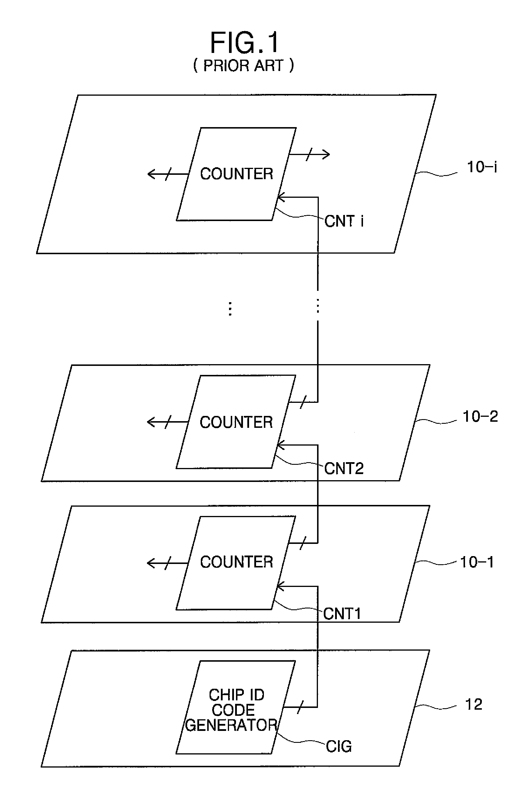
However, since the counters CNT1 to CNTi of the memory chips 10-1 to 10-i are cascade-connected to one another, a next counter generates a delayed output value due to previous counters, thus adversely affecting high-speed operation of the semiconductor memory device.
Also, the circuit configuration of the semiconductor memory device becomes complicated because each of the counters CNT1 to CNTi includes flip-flops.

Method used


Image

  • Semiconductor memory device and method of generating chip enable signal thereof
  • Semiconductor memory device and method of generating chip enable signal thereof
  • Semiconductor memory device and method of generating chip enable signal thereof

Examples


Embodiment Construction

[0044]A semiconductor memory device and a method of generating a chip enable signal thereof according to the present invention will be described more fully hereinafter with reference to the accompanying drawings, in which exemplary embodiments of the invention are shown.

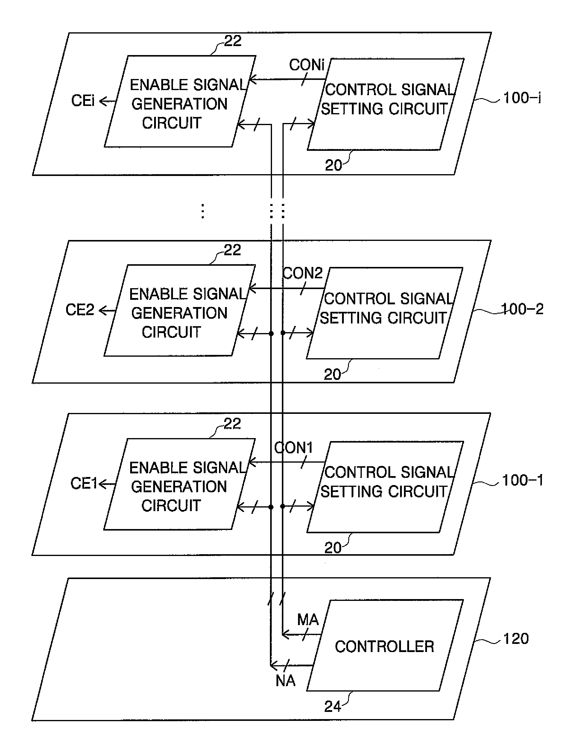
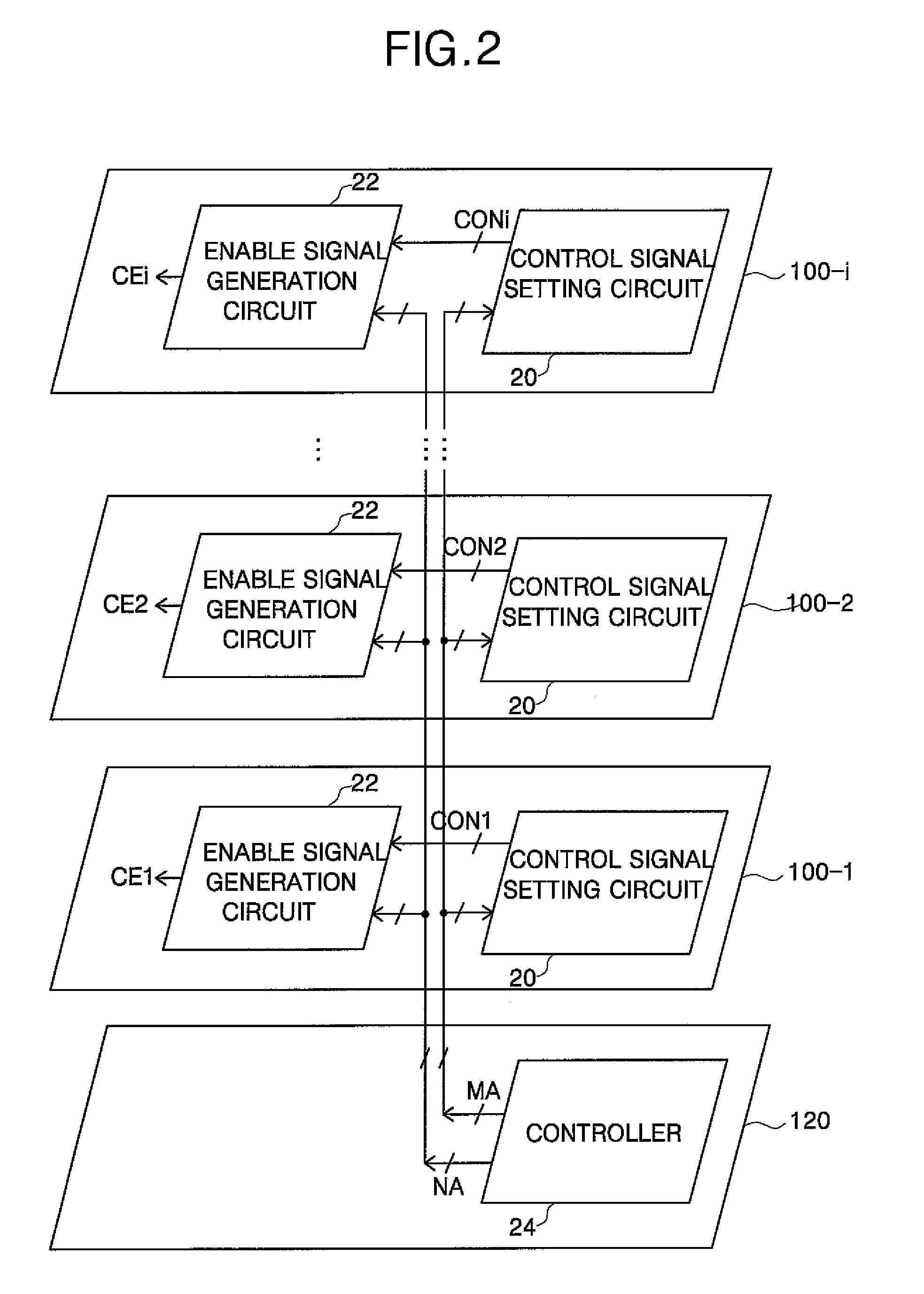
[0045]FIG. 2 is a diagram showing the configuration of a semiconductor memory device according to an exemplary embodiment of the present invention.

[0046]Referring to FIG. 2, the semiconductor memory device includes an i number of memory chips 100-1 to 100-i and an interface chip 120. Each of the memory chips 100-1 to 100-i includes a control signal setting circuit 20 and an enable signal generation circuit 22, and the interface chip 120 includes a controller 24.

[0047]Functions of the blocks shown in FIG. 2 will now be described.

[0048]The controller 24 generates a signal MA in response to an externally applied code signal, for example, an address signal applied through an address input terminal, during a mode register...


PUM


Abstract

Provided are a semiconductor memory device and a method of generating a chip enable signal thereof. The device includes a plurality of memory chips and an interface chip that are stacked. Each of the memory chips includes a control signal setting unit, which sets input signals applied to first and second input nodes as less significant 2-bit control signals of n-bit control signals, performs a logic AND operation on the less significant 2-bit control signals to generate AND operated signals, performs a logic XOR operation on each of the AND operated signals and each bit signal of more significant n−2-bit input signals applied to third to n-th input nodes to set the n−2-bit control signals, outputs the signal applied to the second input node through a first output node, inverts the signal applied to the first input node to output the inverted signal through a second output node, and outputs the more significant n−2-bit input signals through third through n-th output nodes, respectively. The first through n-th output nodes of one of two adjacent memory chips are respectively connected to the first through n-th input nodes of the other of the two adjacent memory chips.

Description

BACKGROUND OF THE INVENTION[0001]1. Field of the Invention[0002]The present invention relates to a semiconductor memory device and, more particularly, to a semiconductor memory device in which a plurality of chips are stacked and packaged and a method of generating a chip enable signal thereof.[0003]2. Description of Related Art[0004]In general, a semiconductor memory device is fabricated by packaging a single chip. Thus, both a memory portion for storing data and a control portion for controlling the input / output of data in / from the memory portion are integrated in the single chip.[0005]However, a semiconductor memory device packaged by stacking a plurality of chips has recently been introduced. In the semiconductor memory device, a control portion is provided in one of the chips, and a memory portion is provided in each of the remaining chips.[0006]In the semiconductor memory device in which the chips are stacked and packaged, each of the chips should include a chip enable signal ...

Claims


Application Information

Patent Timeline
Patent Type & Authority Patents(United States)
IPC IPC(8): G11C5/02
CPCG11C7/1045H03K19/20G11C7/22G11C7/20
Inventor KIM, DOO-GONKIM, YOUN-CHEUL
Owner SAMSUNG ELECTRONICS CO LTD
Learn More