Method and system for X-ray diagnosis of object in which X-ray contrast agent is injected

a contrast agent and x-ray technology, applied in the field of method and system for x-ray diagnosis of objects, can solve the problems of reducing the quality of images, reducing the efficiency of x-ray imaging, and difficulty in obtaining an entire image of such a wide range, so as to reduce the operational burden of physicians

Inactive Publication Date: 2009-12-15
TOSHIBA MEDICAL SYST CORP
View PDF25 Cites 38 Cited by
  • Summary
  • Abstract
  • Description
  • Claims
  • Application Information

AI Technical Summary

Benefits of technology

[0014]It is also preferred that the imaging parameter setting unit is configured to, from the fluoroscopic image obtained by the fluoroscopic scan unit, automatically recognize the region through which the X-ray contrast agent flows and to set the imaging parameters based on a recognized result of the automatic recognition. This automatic recognition allows the flow of the X-ray contrast agent to be traced automatically during the fluoroscopic scan, so that an opening of the X-ray collimator can be adjusted substantially in real time even under the fluoroscopic scan. The automatic recognition of flow of the contrast agent provides a flowing speed and an amount of movement thereof. These pieces of information about the contrast agent are used to automatically determine imaging parameters, such as an X-ray collimating opening at each imaging position and a relative moving speed between the tabletop and the support apparatus, thus remarkably lowering an operational burden on physicians.
[0015]According to a second aspect of the present invention, there is provided a method of X-ray imaging performed by the X-ray diagnostic system comprising an X-ray source irradiating an X-ray; an X-ray detector detecting the X-ray; and a support apparatus configured to support both the X-ray source and the X-ray detector so that both the X-ray source and the X-ray detector are opposed to each other with a space left therebetween, a tabletop on which an object to be examined is laid being located in the space, the object being subjected to injection of an X-ray contrast agent when the object is examined, the method comprising the steps of: relatively moving one of the tabletop and the support apparatus with respect to the other and performing a fluoroscopic scan along a direction predetermined with respect to the object with one of the tabletop and the support apparatus relatively moved with respect to the other, the X-ray contrast agent flowing substantially along the direction, thereby a fluoroscopic image of the object being provided along the direction; setting, at every region to be examined of the object, imaging parameters required for an imaging scan on the basis of the fluoroscopic image, the regions being at least continuous without a gap along the direction determined with respect to the object; and relatively moving one of the tabletop and the support apparatus with respect to the other and, with one of the tabletop and the support apparatus relatively moved with respect to the other, performing the imaging scan on the object on the imaging parameters. This method also provides the similar or identical advantages to those provided by the X-ray diagnostic system.

Problems solved by technology

It is difficult to obtain an entire image of such a wide range through one time of imaging, and several times of imaging is carried out to cover such a wide range.
The halation, if occurring, will degrade the quality of images.
However, an actual blood flow speed is not constant over the wide region from the pelvis to the tiptoes.
Furthermore, such a wide region includes some portions through which blood vessels run in simple and / or complicated ways.
Hence if the lower limb is imaged with the movements of scanning positions in the condition in which the longitudinal opening of the X-ray collimator (that is, the opening of the X-ray collimator in a direction along the lower limb of an object) is held constant, the resultant images suffer from having some portions that are insufficient for diagnosis.
Hence the operations for the imaging are complicated and ballooned.

Method used


Image

  • Method and system for X-ray diagnosis of object in which X-ray contrast agent is injected
  • Method and system for X-ray diagnosis of object in which X-ray contrast agent is injected
  • Method and system for X-ray diagnosis of object in which X-ray contrast agent is injected

Examples


first embodiment

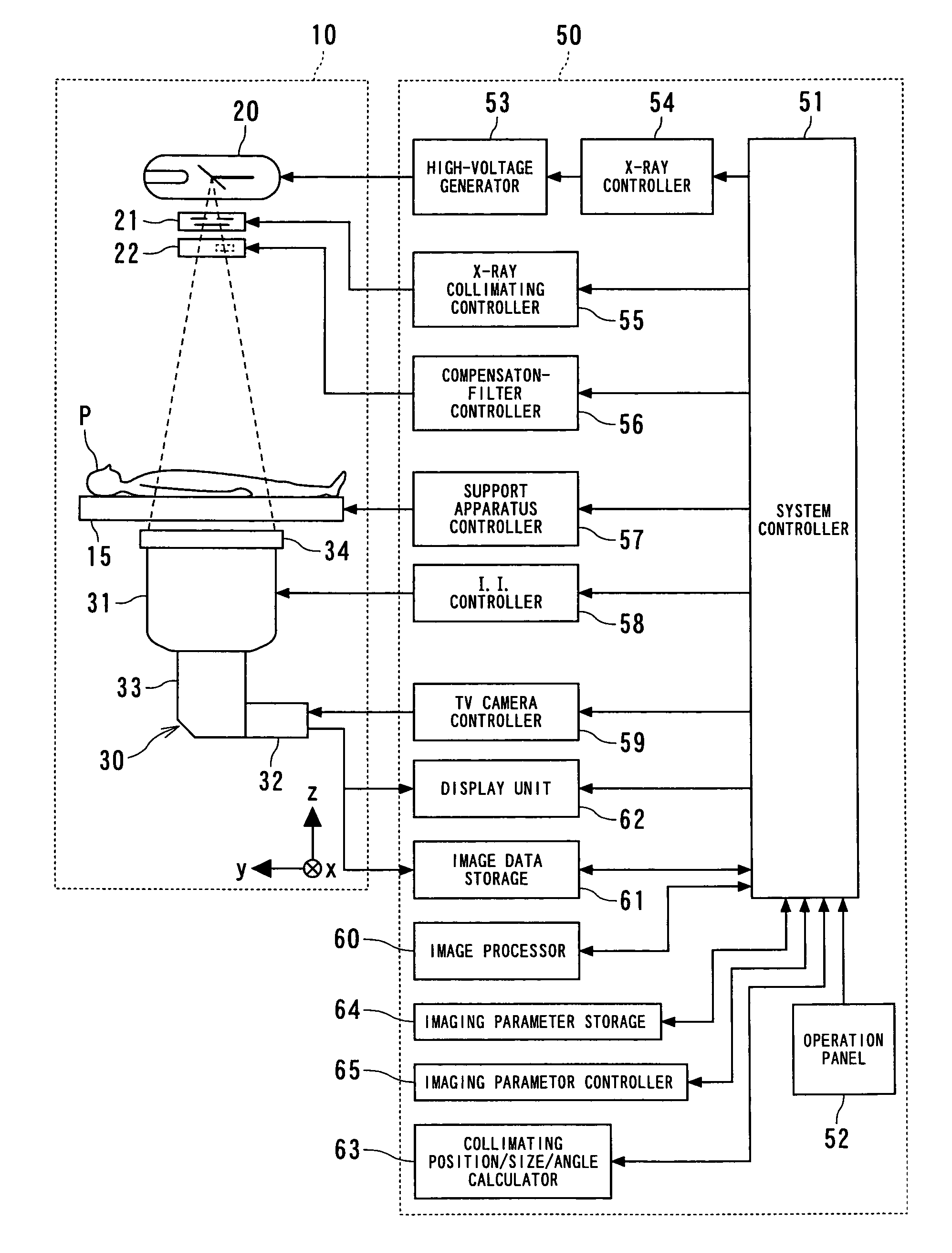
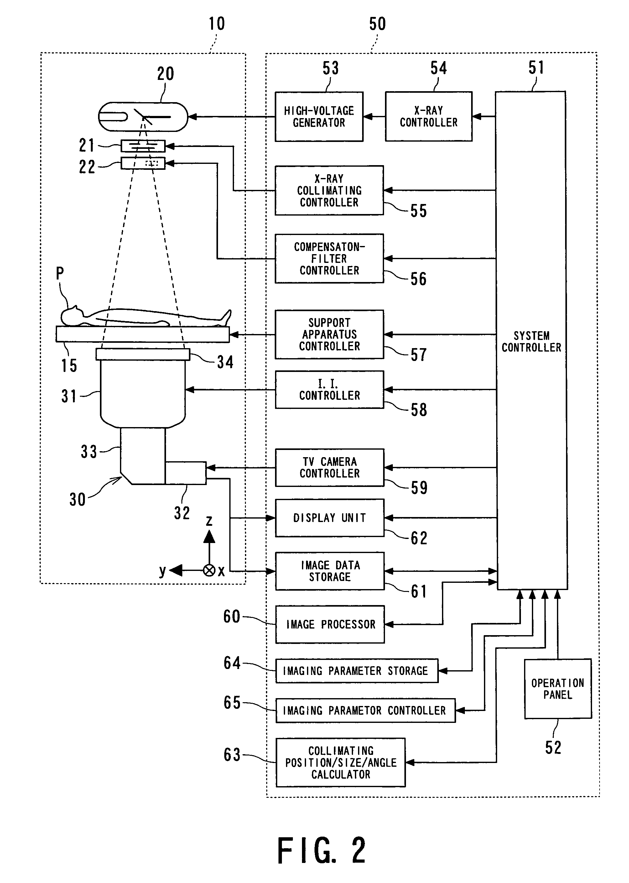
[0035]Referring to FIGS. 1 to 7, a first embodiment of an X-ray diagnostic system according to the present invention will now be detained.

[0036]The X-ray diagnostic system according to the first embodiment is equipped with a support apparatus 10, an X-ray tube 20, an X-ray detector 30 and a controller 50.

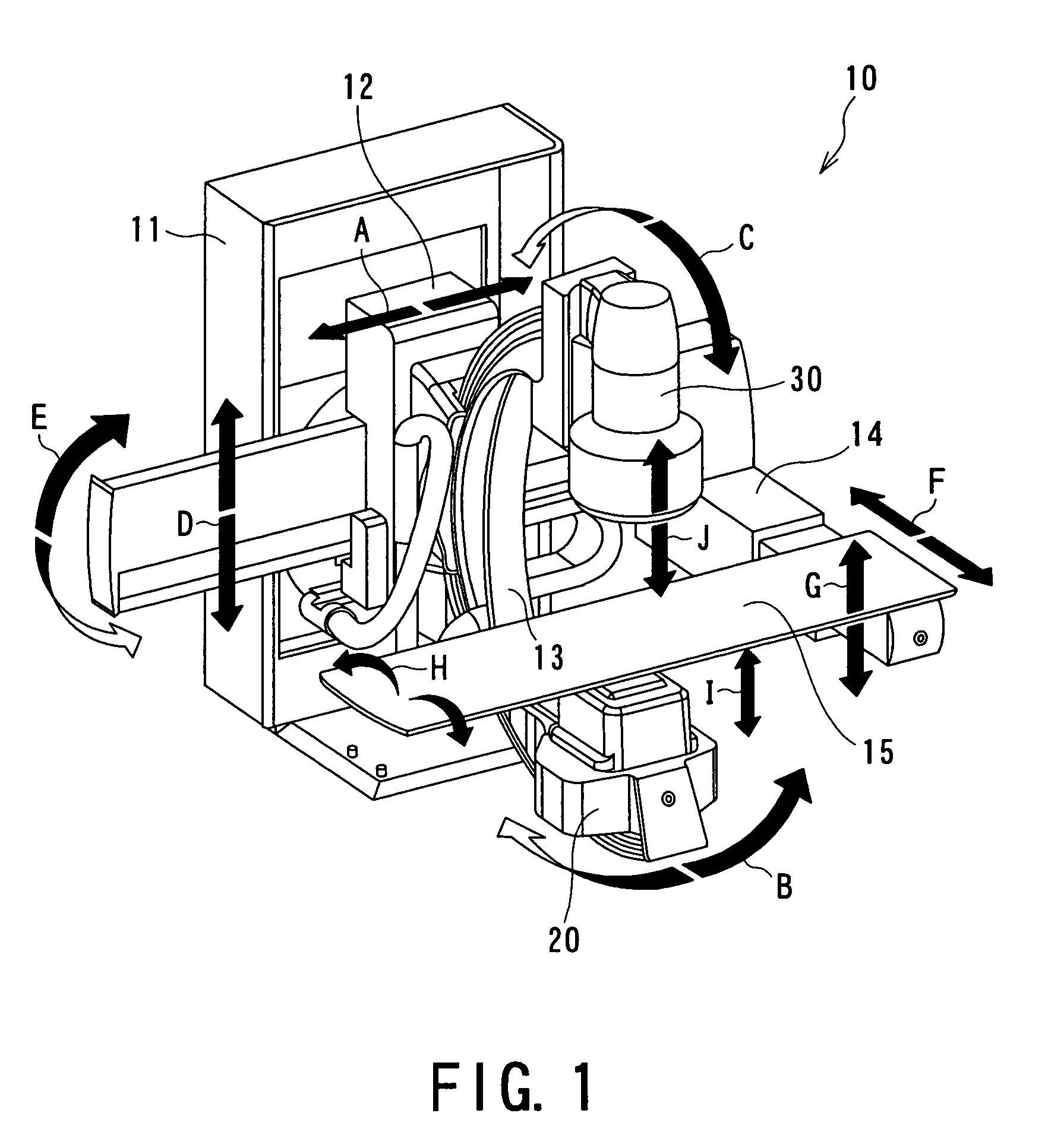
[0037]FIG. 1 is a perspective view outlining a partial configuration of the support apparatus 10 of the X-ray diagnostic system 10. This support apparatus 10 has, as the main components, a supporting main unit 11, a C-shaped arm support mechanism 12, a C-shaped arm 13, a tabletop support mechanism 14, and a tabletop 15.

[0038]The supporting main unit 11 is fixed on the floor and slidably supports the C-shaped arm support mechanism 12 in a direction approximately parallel with the floor (as shown by arrows “A” in FIG. 1). The C-shaped arm 13 is attached to the C-shaped arm support mechanism 12 such that the arm 13 is rotatable along a plane approximately perpendicular to the floor abo...

second embodiment

[0086]Referring to FIGS. 11 to 16, a second embodiment of the X-ray diagnostic system according to the present embodiment will now be described. The present second embodiment features that the routine to set imaging parameters for the imaging scan using a fluoroscopic image acquired through the pre-scan can be automated, not manually performed by an operator.

[0087]In order to automatically set the imaging parameters, the X-ray diagnostic system according to the second embodiment is newly provided, as shown in FIG. 11, with a skeleton processor 70 to extract and process skeletons as patterns of the X-ray contrast agent injected in an object. In addition, the operation panel 52 is equipped with a dead man's switch 71 as an additional switch. The remaining hardware configurations are identical or similar to those used by the first embodiment.

[0088]The skeleton processor 70 is provided as a processor of which main configuration is a computer equipped with a CPU and memories for memorizi...


PUM


Abstract

An X-ray diagnostic system is provided, which uses X-rays to image the lower limb of an object under conditions suitable for a flow of an X-ray contrast agent injected into the object. In the system, a C-shaped arm supports both an X-ray tube and an X-ray detector so that an object-laid tabletop is located between both the tube and the detector. For instance, one of the tabletop and the C-shaped arm is relatively moved with respect to the other so that the object is imaged along a body-axis direction thereof. The apparatus is able to perform a fluoroscopic scan to obtain a body-axis directional fluoroscopic image of the agent-injected object and to set imaging parameters, region by region in the body-axis direction, necessary for an imaging scan using the fluoroscopic image. The imaging parameters are used for the imaging scan of the agent-injected object.

Description

BACKGROUND OF THE INVENTION[0001]1. Technical Field of the Invention[0002]The present invention relates to a method and system for X-ray diagnosis of an object in which an X-ray contrast agent is injected, and in particular, to the method and system preferable to an examination for angiography of a lower limb of the object.[0003]2. Related Art[0004]An X-ray diagnostic system is one of medial imaging modalities that can be utilized for examination and diagnosis for various regions of an object to be examined. One of the examinations carried out by the X-ray diagnostic system is lower-limb angiography of the object.[0005]The lower-limb angiography under the X-ray diagnostic system is carried out such that an X-ray contrast agent is injected into the artery of an object at the groin portion thereof and an X-ray is scanned to track a flow of the contrast agent. Hence the scanning is carried out over a wide range from a region near to the pelvis to the tiptoes. It is difficult to obtain ...

Claims


Application Information

Patent Timeline
Patent Type & Authority Patents(United States)
IPC IPC(8): A61B6/00A61B6/06
CPCA61B6/481A61B6/504A61B6/542A61B6/488A61B6/06A61B6/4441A61B6/4291
Inventor OGAWA, KENICHI
Owner TOSHIBA MEDICAL SYST CORP
Why Eureka
Try Eureka