
Flameless boiler

a boiler and flameless technology, applied in the field of flameless systems, can solve the problem that the brake produces heat on its own, and achieve the effect of recovering more heat from the engin

Inactive Publication Date: 2009-12-29
LEADER ENERGY SERVICES
View PDF8 Cites 21 Cited by
  • Summary
  • Abstract
  • Description
  • Claims
  • Application Information

AI Technical Summary

Benefits of technology

[0006]The present invention seeks to overcome the above disadvantages by providing a flameless boiler in which heat can be derived from an engine, which engine might also be the same engine used for other purposes, and transferred to the water to produce steam. In the present invention, heat is transferred from the engine using heat exchangers to transfer heat from the engine coolant to the water. An exhaust heat exchanger can be used to transfer heat from the engine exhaust to the heat exchange fluid. This allows the present system to recover more heat from the engine. The engine is preferably but not necessarily the engine from the truck or tractor which transports the boiler.
[0008]The water brake of the present invention provides a further advantage that it can run empty when no additional loading of the engine is required or steam generation is unnecessary. This removes the requirement for the usual gear box that disengages the water brake, saving weight and costs for this system.

Problems solved by technology

Further, the shearing of the fluid in the water brake produces heat on its own.

Method used


Image

  • Flameless boiler
  • Flameless boiler
  • Flameless boiler

Examples


Embodiment Construction

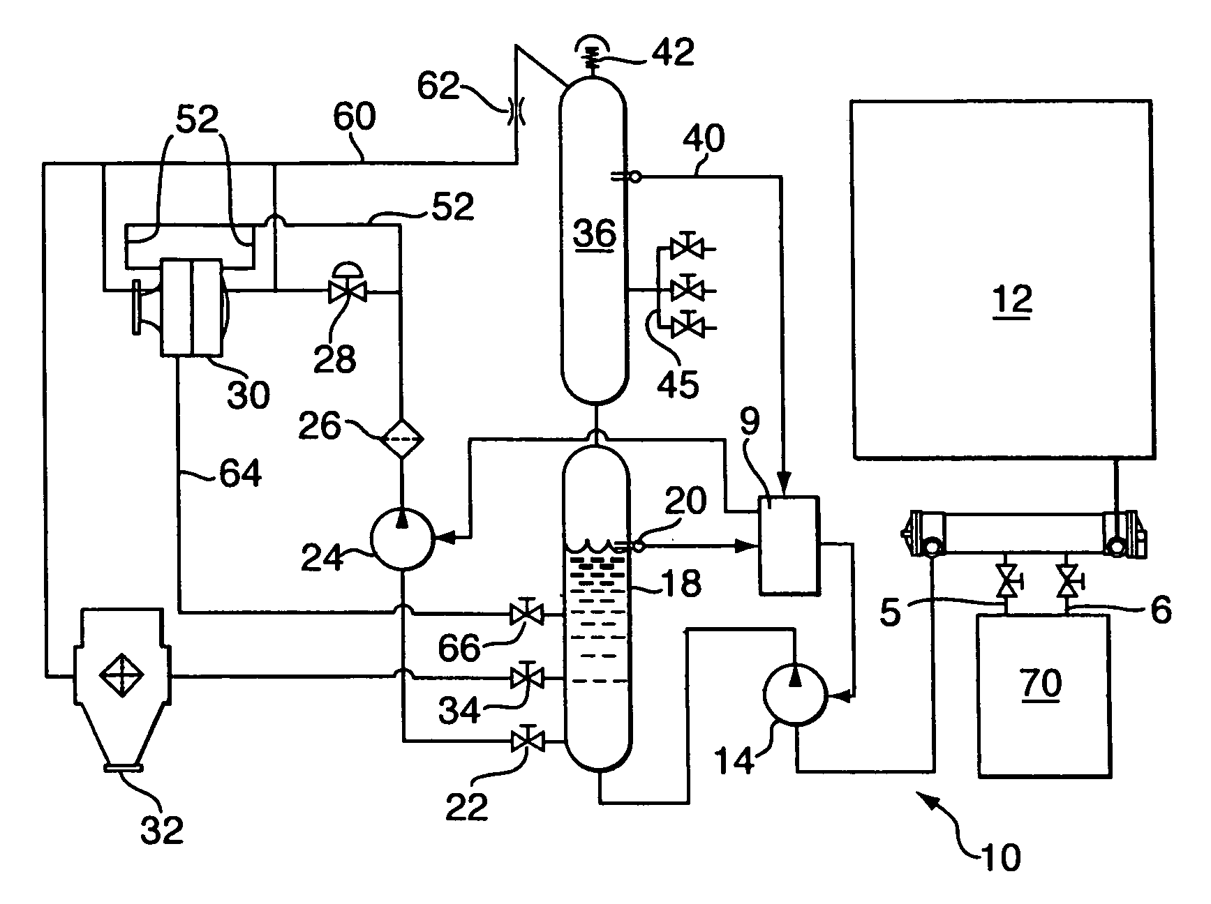
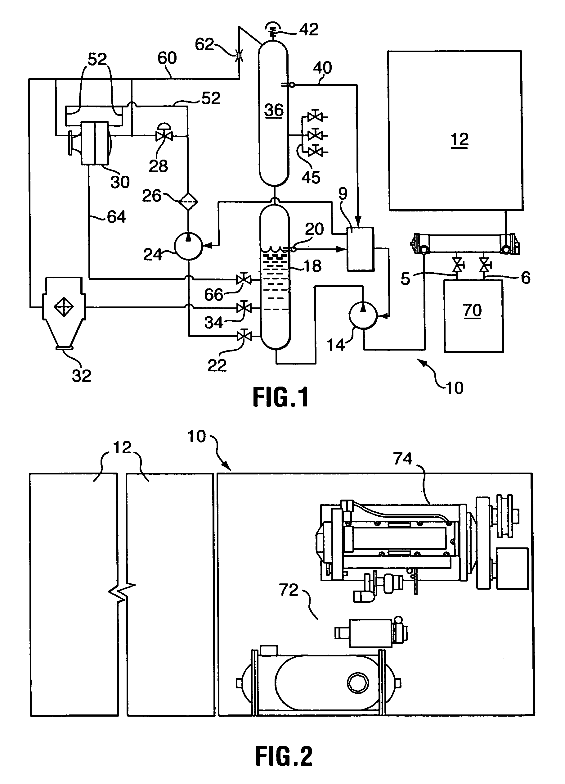
[0017]Reference will now be made to FIG. 1 for a more detailed description of a flameless boiler unit 10. Flameless boiler unit 10 is preferably capable of producing 2.5 million BTU / hr and captures this heat from three sources: engine coolant; exhaust gases; and the use of excess engine horsepower to provide shear heat in the heat transfer fluid, which in this application will normally be water boiled to produce steam.

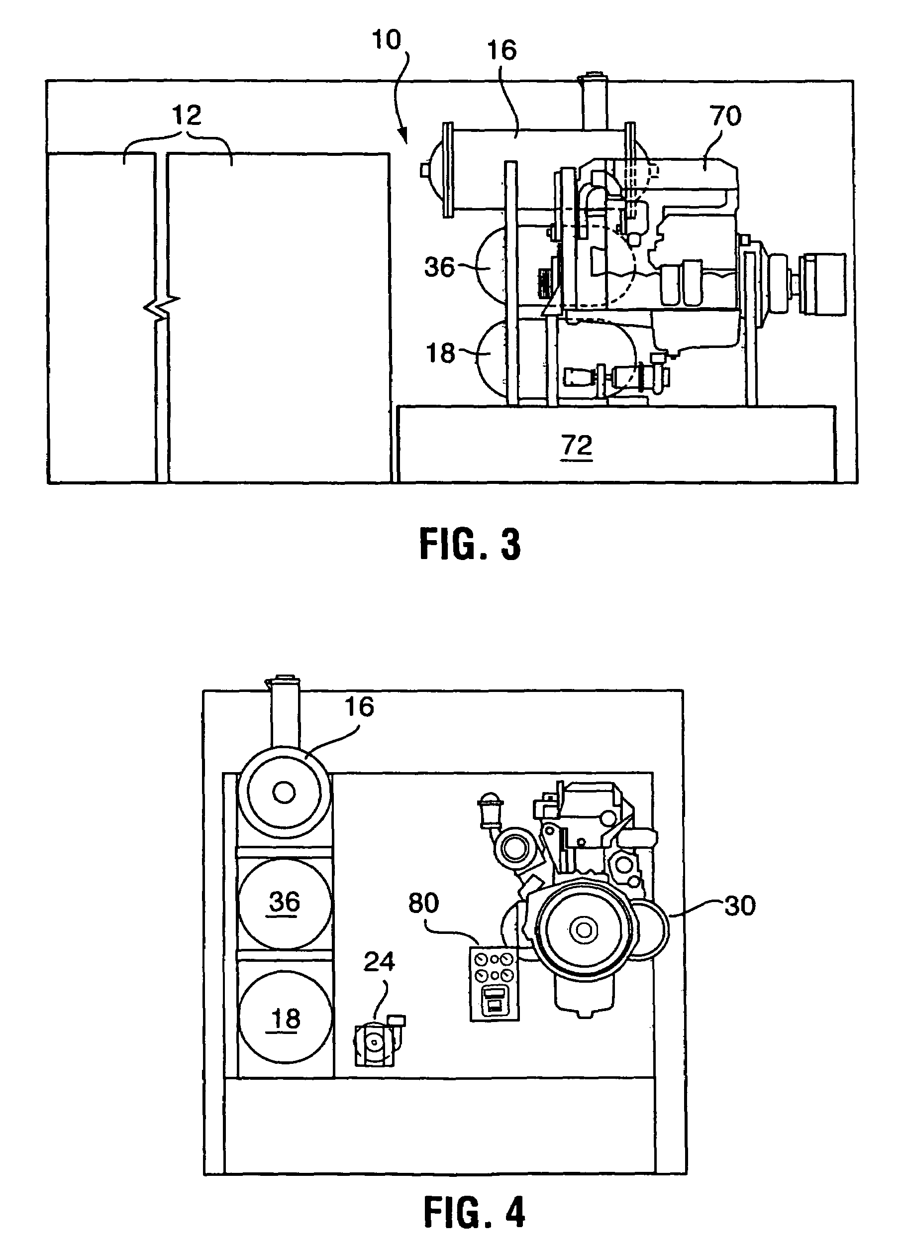
[0018]Heat from engine 70 is transferred to the engine's cooling system in which the coolant will be water, glycol or a mixture of the two. The heated coolant flows through line 5 to a heat exchanger 16, such as a shell and tube heat exchanger well known in the art, and returns to the engine via line 6. Both lines 5 and 6 can be valved to control the flow of coolant from the engine through exchanger 16.

[0019]Cold water for the present system is stored in a storage tank 12. A pump 14 pumps water from storage tank 12 through engine coolant heat exchanger 16. Since the he...


PUM


Abstract

A flameless boiler comprising generator means for generating heat in fluid circulated therethrough by shearing of the fluid; a prime mover drivingly connected to the generator means for shearing of the fluid; a supply reservoir for the fluid; a first pump for circulating the fluid from the supply reservoir to the generator means; and a pressure vessel in fluid communication with the generator means for receiving heated fluid therefrom, the pressure vessel having an outlet for drawing steam therefrom.

Description

FIELD OF THE INVENTION[0001]The present invention relates to a flameless system for boiling water and, more particularly to a flameless boiler in which heat for heating the water comes primarily from the energy produced by a prime mover which may be the engine of the tractor transporting the boiler.BACKGROUND OF THE INVENTION[0002]In a drilling operation, steam is required throughout the drilling process and in maintenance operations after drilling has finished. Present systems generally use a conventional boiler housed in a boiler building to generate and supply the steam. Because conventional boilers use an open combustion process, the boiler building must be located at least 26 metres from the wellhead. This presents the disadvantage that the footprint of the lease site must be enlarged accordingly and more tubing is required to bring the steam to the well bore with attendant thermal losses.[0003]Open combustion boilers have a number of additional disadvantages. The open flame is...

Claims


Application Information

Patent Timeline
Patent Type & Authority Patents(United States)
IPC IPC(8): F22B3/06F22B1/18
CPCF22B3/06F22B1/1807Y02E20/30
Inventor FOSTER, ROBERT JOSEPH
Owner LEADER ENERGY SERVICES
Learn More