Voltage for LCD

a technology of voltage and lcd, applied in the field of circuits, can solve problems such as power supply drop, inability to cope with unexpected power supply drop, and difficulty in controlling the timing of line switching, so as to save manufacturing costs

Inactive Publication Date: 2009-12-29
FUNAI ELECTRIC CO LTD
View PDF9 Cites 0 Cited by
  • Summary
  • Abstract
  • Description
  • Claims
  • Application Information

AI Technical Summary

Benefits of technology

[0009]The present invention aims at providing a circuit for target device or an inverter circuit that can avoid power supply drops and heat generation and save on manufacturing costs with no need of external controls (by a microcomputer etc.).
[0013]This configuration is preferable when the output of the switching transformer drops. Specifically, although normal relationship among respective voltages is first voltage>second voltage>third voltage>fourth voltage, when the output of the switching transformer drops it may become first voltage>third voltage>second voltage>fourth voltage. This occurs in a transient state after the output of a switching transformer was changed, when power supply to a power supply circuit is unstable, or when the entire output of a switching transformer is lowered to save electricity. In such a case, it was necessary to switch the voltage to be inputted to the second constant voltage circuit by means of a switching circuit or the like conventionally, but the configuration described above allows the voltage supply source to be switched automatically and without delay (seamlessly) without having to switch between power sources. This makes it possible to provide a circuit whereby drops in power supply and heat generation can be avoided and thereby the manufacturing cost can be reduced.
[0014]An optional aspect of the present invention provides a circuit wherein the switching transformer is feedback-controlled based on the first voltage. In this configuration, since the second voltage is normally supplied to the second regulator, there is no load on a terminal to which the first voltage for the switching transformer is supplied and there is a load only on a terminal to which the second voltage is supplied. Therefore, when the entire output of a switching transformer is reduced, a drop in the output from the terminal for the second voltage is larger than a drop in the output from the terminal for the first voltage, thus causing a transient state in which the terminal for the second voltage become temporarily unable to supply a sufficient voltage to the second constant voltage circuit. Accordingly, by supplying a voltage based on the second voltage that is lower than the first voltage to the inverter circuit under normal conditions, and using the first voltage that is higher that the second voltage only when the second voltage dropped temporarily, it is possible to save the power consumption and the heat generation in the first constant voltage circuit under normal conditions.
[0015]An optional aspect of the present invention provides a circuit wherein one of or a combination of the first constant voltage circuit and the second constant voltage circuit by means of a regulator IC. That is, if the first and second constant voltage circuits are realized using the regulator IC, the circuit configuration of a circuit is simplified, thus making it easy to design the circuit. Also, less area on the substrate is required for mounting circuit elements, which contributes to the miniaturization of electrical and electronic devices using the circuit of the present invention.

Problems solved by technology

With the switching power supply lines as described in the Japanese Utility Model Registration Application Nos. 3110950 and 3120526, there were problems such as drops in power supply or difficulty in controlling the timing of line switching.
Although it is possible to control the timing for predicted switching as in power on or standby, it is impossible to cope with unexpected power supply drops and the like.
Furthermore, to implement the switching it is necessary to add a switching device such as a transistor, which inevitably increases the manufacturing cost.
This is disadvantageous in designing the circuit and also the electric power consumed for heat generation is wasted.
This heat generation problem also exists in the case of using a Zener diode as described in the Japanese Utility Model Registration Application No. 3120526.

Method used


Image

  • Voltage for LCD
  • Voltage for LCD
  • Voltage for LCD

Examples


Embodiment Construction

[0023]The detailed description set forth below in connection with the appended drawings is intended as a description of presently preferred embodiments of the invention and is not intended to represent the only forms in which the present invention may be constructed and or utilized.

[0024]For purposes of illustration, programs and other executable program components are illustrated herein as discrete blocks, although it is recognized that such programs and components may reside at various times in different storage components, and are executed by the data processor(s) of the computers.

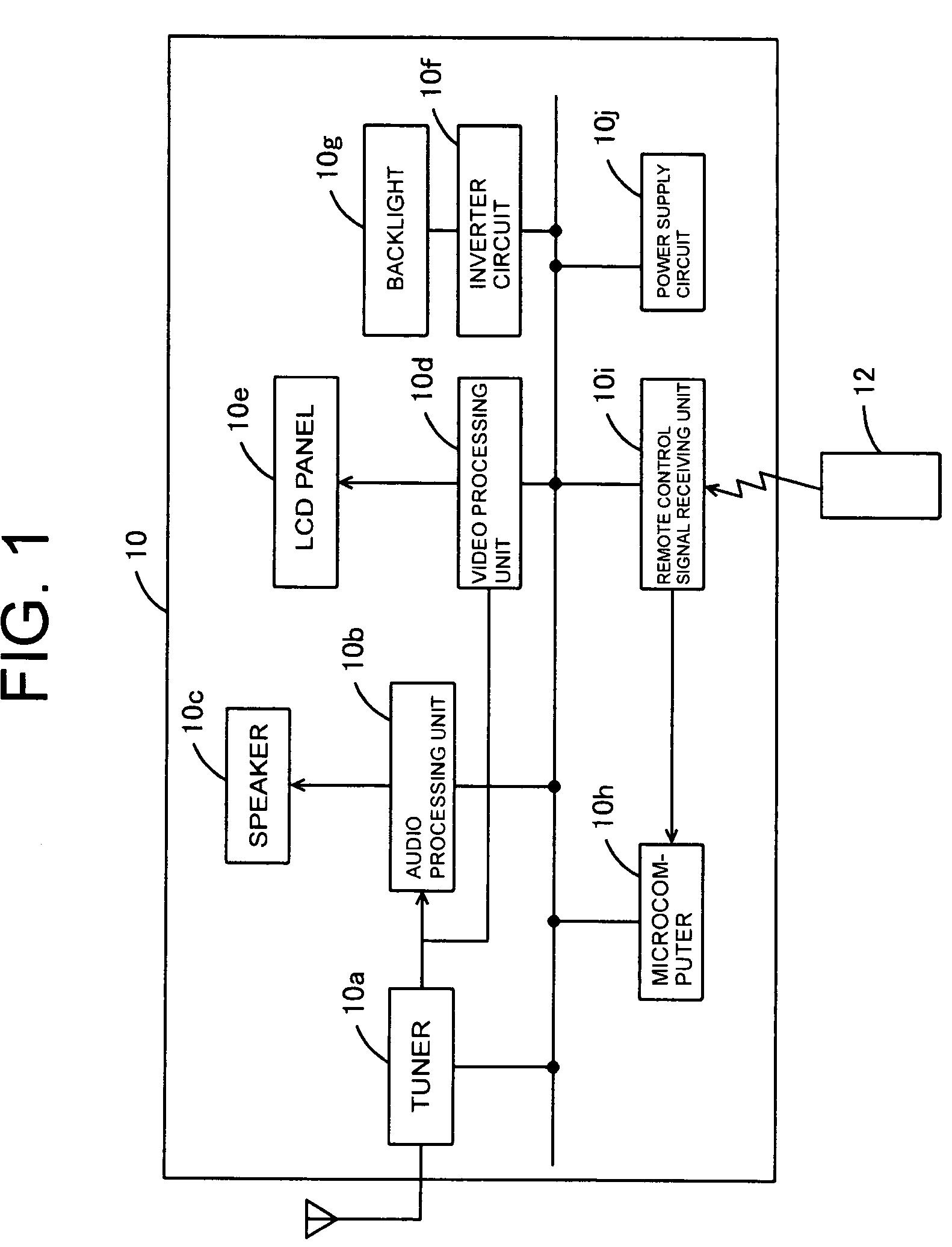
[0025]Embodiments of the present invention will be described below in the following order:[0026](1) Configuration of an LCD television[0027](2) Configuration and operation of a voltage supply stabilizing circuit[0028](3) Summary

[0029](1) Configuration of an LCD Television:

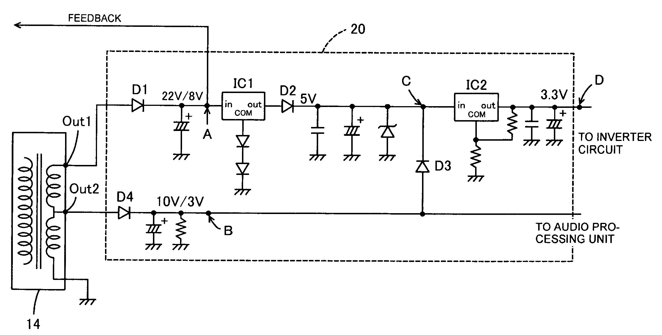
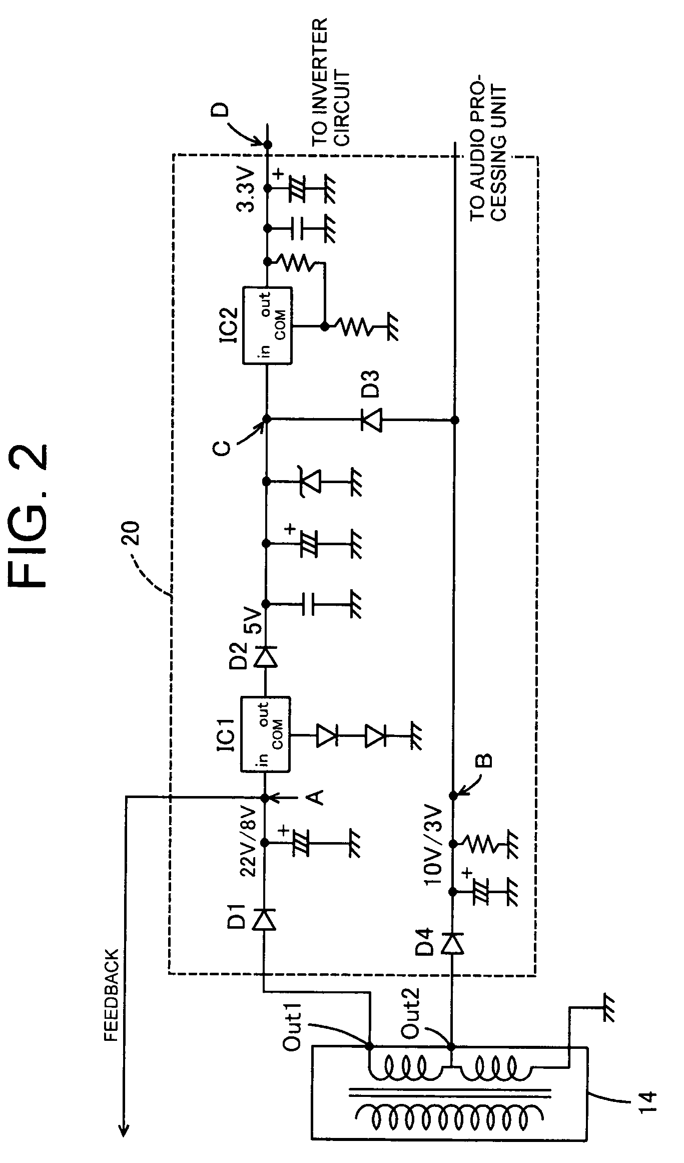
[0030]With reference to FIGS. 1 through 3, a voltage supply stabilizing circuit 20 of the present invention is described below taking...


PUM


Abstract

A circuit that can avoid drops in power supply and heat generation and save on manufacturing costs with no need of external controls are configured such that: a switching transformer has a terminal that produces an output of 22V at power-on and an output of 8V during standby and a terminal that produces an output of 10V at power-on and an output of 3V during standby; the output of 22V or 8V is lowered to 5V by a regulator IC1 and applied (input) to a regulator IC2; an input of 10V or 3V is produced at the regulator IC2; at power-on, the regulator IC2 lowers 10V to 3.3V and supplies the lowered 3.3V to the inverter circuit 10f; and during standby, a regulator IC lowers 8V to 3.3V and supplies the lowered 3.3V to the inverter circuit 10f.

Description

CROSS-REFERENCES TO RELATED APPLICATIONS[0001]The present application is related to the Japanese Patent Application No. 2006-192992, filed Jul. 13, 2006, the entire disclosure of which is expressly incorporated by reference herein.BACKGROUND OF THE INVENTION[0002]1. Field of the Invention[0003]The present invention relates to a circuit, and more specifically relates to a circuit that supplies a voltage outputted from a switching transformer to a target device and a circuit that stabilizes voltage supply to an inverter circuit of an LCD apparatus.[0004]2. Description of the Related Art[0005]Conventionally, if there is a possibility that a voltage to be supplied to a predetermined device will drop, power voltage supply is stabilized by switching among a plurality of power voltage supply lines with a transistor each time a supply voltage drops (as disclosed in Japanese Utility Model Registration Application No. 3110950), or by controlling the on / off of a regulator IC with a microcomput...

Claims


Application Information

Patent Timeline
Patent Type & Authority Patents(United States)
IPC IPC(8): G01R1/20G06F3/038
CPCH04N5/63
Inventor MIYAMOTO, HITOSHI
Owner FUNAI ELECTRIC CO LTD
Why Eureka
Try Eureka