Multi-object wavefront sensor with spatial filtering

a multi-object wavefront sensor and spatial filtering technology, applied in the field of high-resolution wide-field adaptive optic imaging system based on compact multi-reference wavefront sensor, can solve the problems of high cost, unwanted light from parasitic source reflection, and high cost, and achieve the effect of high cos

Active Publication Date: 2009-12-29
OWNER PETERSEN METTE +2
View PDF7 Cites 42 Cited by
  • Summary
  • Abstract
  • Description
  • Claims
  • Application Information

AI Technical Summary

Benefits of technology

[0025]The shortcomings of single reference systems in the severely restricted field of corrected view is solved with multi-conjugate adaptive optics (MCAO) systems, however this is at high cost and gives bulky instruments, especially problematic in ophthalmology. Another problem, especially in the study of the human eye is unwanted light from parasitic source reflections and light from unwanted object regions. The present invention solves both these problems by firstly using an array of collimator lenses making it possible to spatially filter the light from all guide stars using one variable pinhole, and secondly this arrangement makes it possible to use a single camera to image the Hartmann patterns of multiple reference sources.

Problems solved by technology

The shortcomings of single reference systems in the severely restricted field of corrected view is solved with multi-conjugate adaptive optics (MCAO) systems, however this is at high cost and gives bulky instruments, especially problematic in ophthalmology.
Another problem, especially in the study of the human eye is unwanted light from parasitic source reflections and light from unwanted object regions.

Method used


Image

  • Multi-object wavefront sensor with spatial filtering
  • Multi-object wavefront sensor with spatial filtering
  • Multi-object wavefront sensor with spatial filtering

Examples


example 1

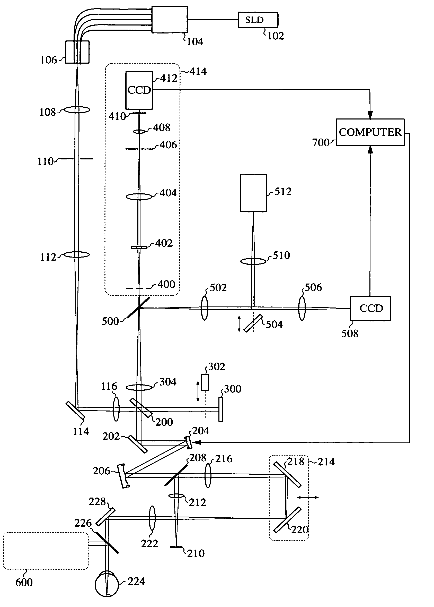
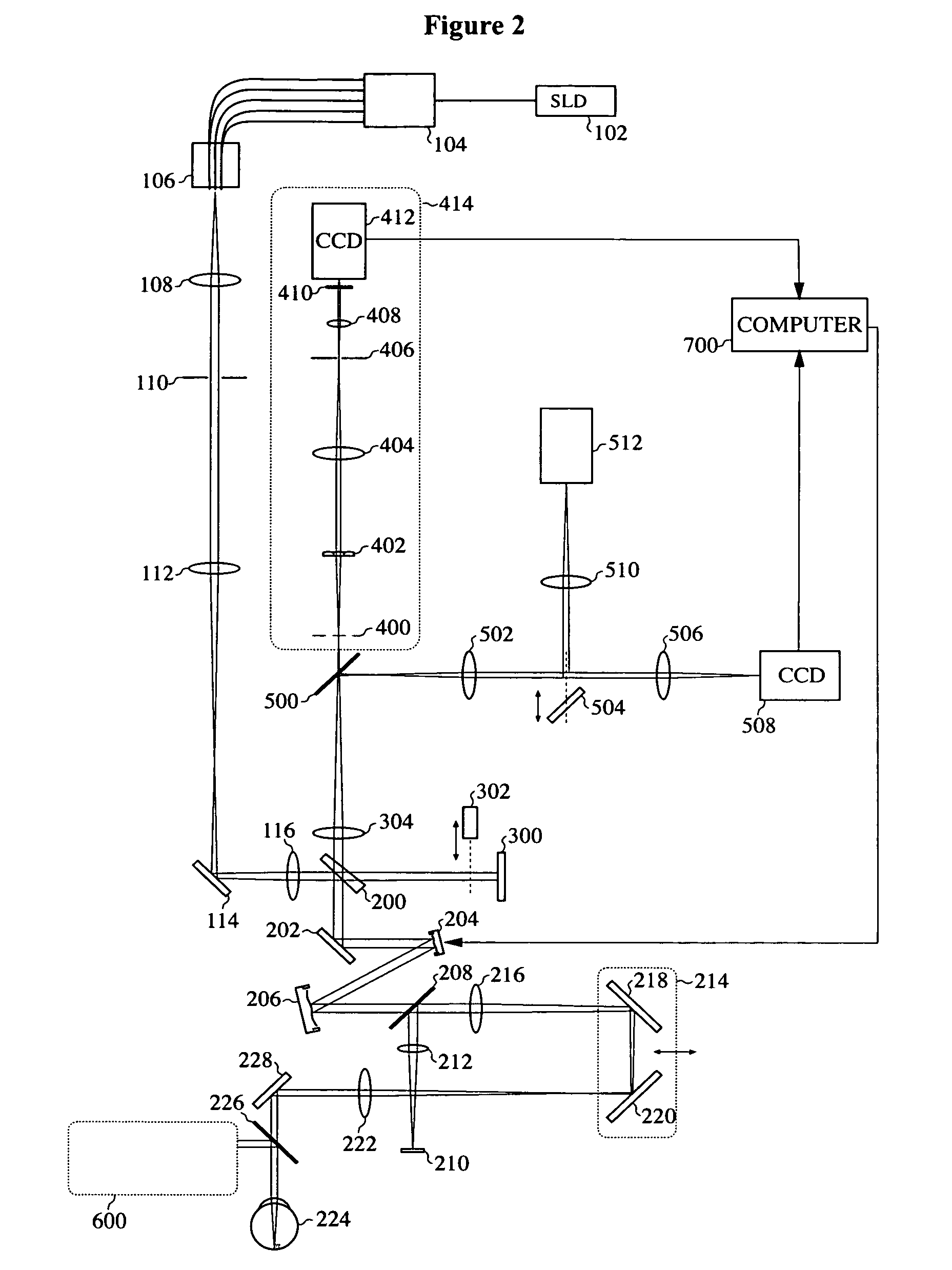
[0043]In the following we describe, the use of the sensor in connection with retinal imaging (overview in FIG. 2).

Light Delivery

[0044]As shown in FIG. 2, continuous relatively broadband near-infrared light from a super-luminescent diode (SLD) 102 is fed through a pigtailed single mode fiber to a 1-to-5 single mode fiber splitter 104. The five single mode fibers are connected to an adjustable fiber holder 106 that feeds the light through five single mode fibers. The fiber ends, arranged in a cross with a center-to-center displacement of 3.5 mm, are positioned at the focal plane of a collimating lens 108, and light fed through the fiber ends forms five separate collimated ray-bundles after the collimating lens 108. The bundles pass a pupil 110 and are coupled into the main light path via lens 112, a mirror 114, and a lens 116.

[0045]Part of the light is diverted by a wedge beam splitter (WBS) 200 and a mirror 202 towards two deformable mirrors (DM) 204 and 206 (OKO Technologies, Delft,...

example 2

[0049]A simulation was made (see FIG. 3a) using the optical software package ZEMAX (ZEMAX Development Corporation, Bellevue Wash., USA) of the layout of the multiple focused source images in the plane of the WFS pinhole 406. The scale bar is 250 microns.

[0050]FIG. 3b shows actual images of the multiple focused source images, the two leftmost images just in front of the plane of the WFS pinhole 406, the middle image in the plane of the WFS pinhole 406, and the two rightmost images just after the plane of the WFS pinhole 406. FIG. 4a shows a ZEMAX simulation of the layout of the multiple Hartmann images on the WFS camera 412. Scale bar is 6900 microns. FIG. 4b shows the real multiple reference Hartmann images on the WFS camera 412 and FIG. 4c shows the real multiple measurement Hartmann images on the WFS camera 412.


PUM


Abstract

The present invention relates to an adaptive optics sensor intended for simultaneous detection of several wavefronts on a common camera target. The sensor is intended for use in connection with multi-conjugate adaptive optics (MCAO), where several wavefront measurements are needed at the same time. The sensor includes a spatial filter taking out signals resulting from parasitic reflections of the reference sources and from unwanted parts of the object.

Description

CROSS-REFERENCE TO RELATED APPLICATIONS[0001]This application claims priority from U.S. provisional application Ser. No. 60 / 791,727 filed Apr. 13, 2006, which is incorporated herein by reference.BACKGROUND OF THE INVENTION[0002]1. Field of the Invention[0003]The present invention relates to a high-resolution wide field adaptive optics imaging system based on a compact multi-reference wavefront sensor.[0004]The shortcomings of single reference systems in the severely restricted field of corrected view is solved with multi-conjugate adaptive optics (MCAO) systems; however this is at high cost and gives bulky instruments, especially problematic in ophthalmology. Another problem, especially in the study of the human eye, is unwanted light from parasitic source reflections and light from unwanted object regions.[0005]2. Description of the Related Art[0006]The main purpose of an adaptive optics (AO) system is to correct for dynamical optical aberrations that blur the image of a normally e...

Claims


Application Information

Patent Timeline
Patent Type & Authority Patents(United States)
IPC IPC(8): G01B11/02A61B3/10
CPCG01J9/00A61B3/156A61B3/103
Inventor OWNER-PETERSEN, METTETHAUNG, JORGENPOPOVIC, ZORAN
Owner OWNER PETERSEN METTE
Why Eureka
Try Eureka