Cutting tool and associated tool head

a cutting tool and tool head technology, applied in the field of cutting tools, can solve the problems of achieve the unsatisfactory supply of cooling agent to the cutting inser

Active Publication Date: 2010-01-05
SANDVIK INTELLECTUAL PROPERTY AB
View PDF31 Cites 54 Cited by
  • Summary
  • Abstract
  • Description
  • Claims
  • Application Information

AI Technical Summary

Benefits of technology

[0004]Thus, the basic object of this invention is to provide a cutting tool of the above-mentioned kind, which, in relation to prior known cutting tools of the kind in question, has improved characteristics as regards supply of cooling agent to the cutting insert included in the tool.

Problems solved by technology

In grooving operations and parting operations, when a very narrow cutting edge penetrates deeply into the workpiece, such known cutting tools often achieve an unsatisfactory supply of cooling agent to the cutting insert.
A drawback of this solution is that the cooling agent, before hitting the cutting insert, hits the chips being removed by the cutting insert, so that a major part of the cooling agent jet is deflected and, thus, an unsatisfactory supply of cooling agent to the cutting insert is achieved.

Method used


Image

  • Cutting tool and associated tool head
  • Cutting tool and associated tool head
  • Cutting tool and associated tool head

Examples


Embodiment Construction

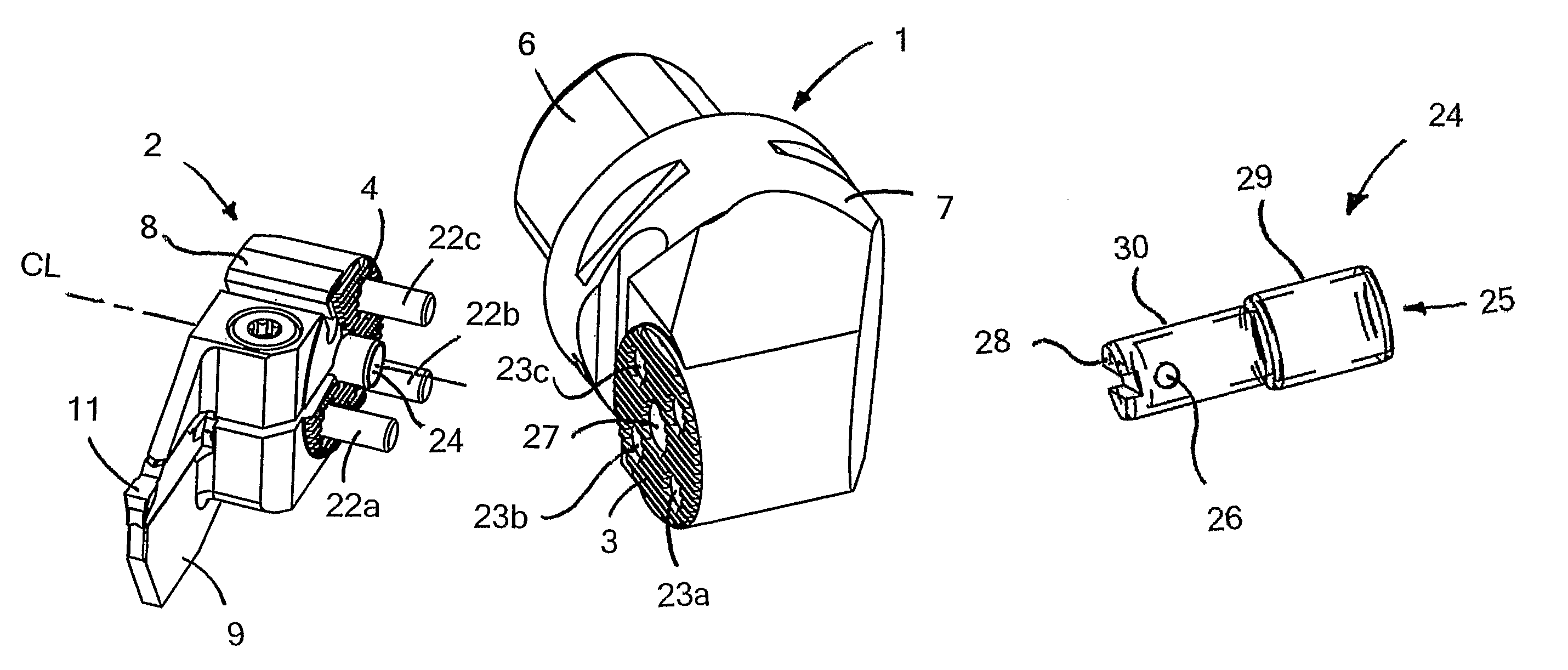
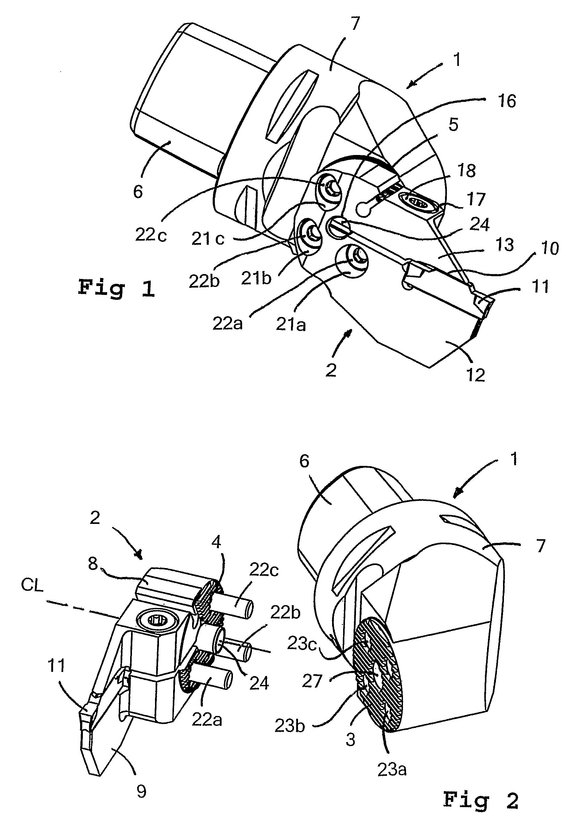
[0014]FIGS. 1 and 2 illustrate a tool for cutting or chip removing metal machining, more exactly a cutting tool for turning operations in form of parting operations and grooving operations. The cutting tool comprises a coupling part 1, which is detachably connected or interconnectable to a tool head 2. In the shown embodiment the parts 1,2 are connectable with each other via serration surfaces 3, 4. Thus, the coupling part 1 has a first serration surface 3 and the tool head 2 has a second serration surface 4. When these surfaces 3, 4 are brought into engagement with each other, they are part of an interface, designated 5, between the parts 1 and 2. The cutting tool is intended to, with the coupling part 1 thereof, be mounted in a machine tool (not shown), for instance a multi operation lathe. For this purpose, the coupling part is provided with a rear coupling piece 6, which is joined to a larger front body 6.

[0015]The tool head 2 is formed in one piece with a relatively thick basic...


PUM

PropertyMeasurementUnit
widthaaaaaaaaaa
widthaaaaaaaaaa
angleaaaaaaaaaa

Abstract

A cutting tool for parting and grooving operations of the kind including a coupling part, which is intended for mounting the cutting tool in a machine tool, and a tool head detachably connected to the coupling part. The tool head includes a basic holder part and, joined to the basic holder part, a blade part, in front portion of which an insert pocket is formed, in which a cutting insert is fastenable. The cutting tool also includes means for supplying cooling agent to the cutting insert. The cooling agent supplying means includes a tube member, which is mounted in a recess, which is transverse to the longitudinal direction of the blade part and arranged in the tool head. The tube member has an inlet for connection to a cooling agent source and an outlet for leading the cooling agent in a direction towards the cutting insert.

Description

FIELD OF THE INVENTION[0001]The present invention is related to a cutting tool for parting and grooving operations of the kind comprising a coupling part, which is intended for mounting the cutting tool in a machine tool, and a tool head detachably connected to the coupling part, the tool head comprising a basic holder part and, joined to the basic holder part, a blade part, in the front portion of which an insert pocket is formed, in which a cutting insert is fastenable, the cutting tool also comprising means for supplying cooling agent to the cutting insert.BACKGROUND OF THE INVENTION AND PRIOR ART[0002]For tools of the above-mentioned kind, during the machining operation there is supplied, for various reasons, some form of cooling agent to the cutting insert(s) in engagement with the workpiece. The cooling agent may whenever applicable consist of cooling liquid, cooling gas, or a liquid / gas mixture. For instance, in some cases cooling liquid is supplied in order to cool the cutti...

Claims


Application Information

Patent Timeline
Patent Type & Authority Patents(United States)
IPC IPC(8): B23B27/10B23B27/04B23BB32B27/10
CPCB23B27/10B23B29/043B23B29/046Y10T407/2282Y10T408/44Y10T407/225Y10T407/25Y10T407/227Y10T407/14Y10T82/16065Y10T407/2274Y10T407/15B23B27/00B32B27/10
Inventor BERMINGE, ERIKHANSSON, PER
Owner SANDVIK INTELLECTUAL PROPERTY AB
Why Eureka
Try Eureka