Vacuum chamber stage with application of vacuum from below

a vacuum chamber and vacuum chamber technology, applied in the field of equipment, can solve the problems of inconvenient direct attachment of such large tubes to the vacuum chamber stage, and achieve the effect of improving vacuum and precision, and facilitating the creation of lower pressur

Inactive Publication Date: 2010-01-05
NEW WAY MACHINE COMPONENTS
View PDF21 Cites 20 Cited by
  • Summary
  • Abstract
  • Description
  • Claims
  • Application Information

AI Technical Summary

Benefits of technology

[0025]This embodiment includes an additional novelty which provides for conductance of air pressure or molecules away from the substrate or the possibility to process both sides of the wafer at one time by providing thru a hole in the base reference member opposite the area of interest. We believe that first embodiment described in the above-cited US 2006/0060259 A1 can realize 10−7 torr with vacuum services coupled to the va

Problems solved by technology

Because very low pressure requires large aperture conductance it can be in

Method used


Image

  • Vacuum chamber stage with application of vacuum from below
  • Vacuum chamber stage with application of vacuum from below
  • Vacuum chamber stage with application of vacuum from below

Examples


Embodiment Construction

[0037]Preferred embodiments of the present invention will now be set forth in detail with reference to the drawings, in which like reference numerals refer to like elements or steps throughout.

[0038]Pump from Below without Outside Vacuum

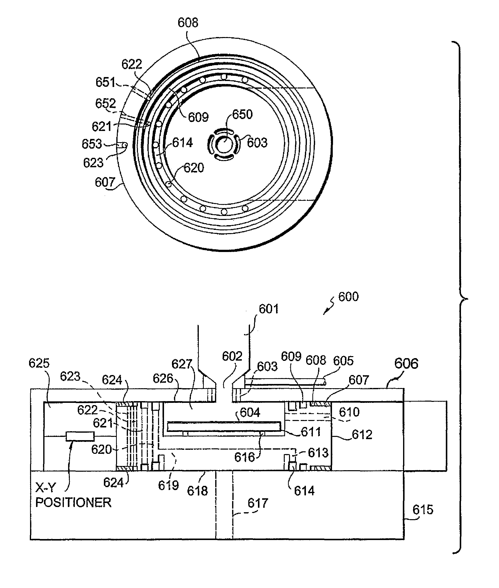
[0039]This embodiment is shown in FIG. 6. This novelty allows large aperture conductance 617 to be ported into the vacuum chamber stage 612 though the sub base plate 615 without any physical contact. This is accomplished by repeating the air bearing 607 and differentially pumped grooves 608, 609, 614 on the underside of the vacuum chamber stage 612. This is essentially two opposed mirror images. This large aperture 617 though the sub base plate 615 can then be ported in to the last differentially pumped groove 614 or into the chamber 627 directly. This dramatically improves vacuum conductance in the chamber and improves stage motion performance by minimizing the vacuum tube size. The stage no longer sees the atmospheric pressure so the air bearing la...


PUM


Abstract

A stage for processing a substrate, especially useful for vacuum applications, has a recess just large enough to hold a substantially flat substrate and a chuck or holder, but not much more. The perimeter of both top and bottom of the stage has air bearing surfaces separated from the recess by differentially pumped grooves and seal lands. The air bearing lands are guided between two reference surfaces and the seal lands, being substantially coplanar, create a resistance to flow between the bearings and the recess. On the other side of one of the reference plates mounts the radiation source or process. The opposite reference plate may have a large aperture, non-contact pumping port. This improves vacuum capability and stage precision. The stage may operate in a vacuum environment itself or can provide multiple stages moving between processes or inspection steps within the same tool or process sequence.

Description

REFERENCE TO RELATED APPLICATIONS[0001]The present application claims the benefit of U.S. Provisional Patent Application No. 60 / 796,563, filed May 2, 2006. Related information is disclosed in U.S. patent application Ser. No. 11 / 206,296, filed Aug. 18, 2005 (U.S. Patent Application Publication No. 2006 / 0060259 A1), currently pending. The disclosures of both of the above-captioned applications are hereby incorporated by reference in their entireties into the present disclosure.FIELD OF THE INVENTION[0002]This invention relates generally to equipment used in the manufacture of semiconductor devices and masks and more particularly to equipment used in vacuum processes. Applications are anticipated in areas including, but not limited to, ion implant and milling, deposition, etch, ash, clean, lithography, inspection and CD SEM.BACKGROUND OF THE INVENTION AND DESCRIPTION OF RELATED ART[0003]Because of the shrinking feature sizes in semiconductor wafers, greater degrees of precision are req...

Claims


Application Information

Patent Timeline
IPC IPC(8): G01F23/00G01K5/08G01K5/10G21K5/08G21K5/10
CPCH01J37/18H01J37/185H01J37/20H01J2237/2006H01J2237/201H01J2237/20207H01J2237/20221H01J2237/20292H01J2237/204
Inventor DEVITT, ANDREW J.
Owner NEW WAY MACHINE COMPONENTS
Why Eureka
Try Eureka