PZT MEMS resonant Lorentz force magnetometer

Inactive Publication Date: 2010-01-05
UNITED STATES OF AMERICA THE AS REPRESENTED BY THE SEC OF THE ARMY
View PDF4 Cites 54 Cited by
  • Summary
  • Abstract
  • Description
  • Claims
  • Application Information

AI Technical Summary

Benefits of technology

[0013]The embodiments of the invention provide a lead zirconate titanate (PZT) MEMS resonant Lorentz force magnetometer that avoids conventional design flaws and functions properly as a quasi-st

Problems solved by technology

Moreover, application of the current

Method used


Image

  • PZT MEMS resonant Lorentz force magnetometer
  • PZT MEMS resonant Lorentz force magnetometer
  • PZT MEMS resonant Lorentz force magnetometer

Examples


Embodiment Construction

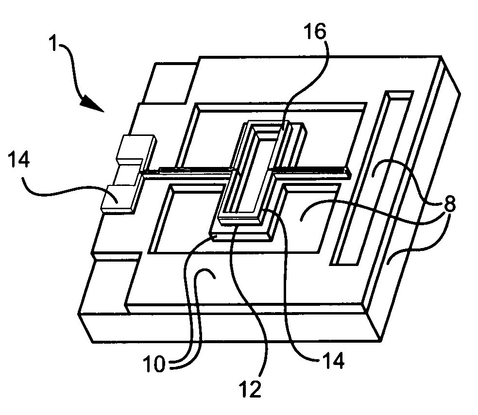
[0037]The embodiments of the invention and the various features and advantageous details thereof are explained more fully with reference to the non-limiting embodiments that are illustrated in the accompanying drawings and detailed in the following description. It should be noted that the features illustrated in the drawings are not necessarily drawn to scale. Descriptions of well-known components and processing techniques are omitted so as to not unnecessarily obscure the embodiments of the invention. The examples used herein are intended merely to facilitate an understanding of ways in which the embodiments of the invention may be practiced and to further enable those of skill in the art to practice the embodiments of the invention. Accordingly, the examples should not be construed as limiting the scope of the embodiments of the invention.

[0038]As mentioned, there remains a need for a novel MEMS magnetometer device capable of mapping magnetic fields in various applications, and wh...


PUM


Abstract

A MEMS magnetometer comprises a deflectable resonator comprising a base layer; a Lorentz force (LF) drive conductor attached to the base layer; and a piezoelectric sensor attached to the base layer and electrically isolated from the LF drive conductor. The LF drive conductor comprises conductive material configured for receiving a current at a mechanical resonant frequency of the device capable of causing mechanical deformation of the deflectable resonator, wherein the current causes formation of Lorentz forces in a presence of a magnetic field, and wherein the deflectable resonator is mechanically deformed as a result of the formation of the Lorentz forces. The mechanical deformation of the deflectable resonator generates a detectable piezoelectric electrical signal that is proportional to the magnitude of the magnetic field.

Description

GOVERNMENT INTEREST[0001]The embodiments of the invention described herein may be manufactured, used, and / or licensed by or for the United States Government.BACKGROUND OF THE INVENTION[0002]1. Field of the Invention[0003]The embodiments of the invention generally relate to microelectromechanical systems (MEMS) devices and microelectronic devices, and, more particularly, to Lorentz force magnetometer devices.[0004]2. Description of the Related Art[0005]Conventional MEMS Lorentz force magnetometer designs, such as those described in U.S. Pat. No. 5,959,452, issued to Givens et al. on Sep. 28, 1999, the complete disclosure of which is herein incorporated by reference, describe both optical and capacitive transduction schemes. This capacitive design has achieved a sensor resolution of approximately 1 μT using a drive current of 1 mA and a Q-factor of 20,000, such as suggested by Wickenden et. al, “An Extremely Sensitive MEMS Magnetometer for use as an Orientation Sensor on Projectiles,”...

Claims


Application Information

Patent Timeline
IPC IPC(8): H01L41/08
CPCG01R33/028G01R33/0286H01L41/1132H10N30/302
Inventor PULSKAMP, JEFFREY S.
Owner UNITED STATES OF AMERICA THE AS REPRESENTED BY THE SEC OF THE ARMY
Why Eureka
Try Eureka