
Bead pack brazing with energetics

a technology of energetics and beads, applied in the direction of soldering apparatus, manufacturing tools, borehole/well accessories, etc., can solve the problems of high energy consumption and process required specialized equipment, and achieve the effect of reducing energy consumption and

Inactive Publication Date: 2010-01-12
BAKER HUGHES INC
View PDF24 Cites 61 Cited by
  • Summary
  • Abstract
  • Description
  • Claims
  • Application Information

AI Technical Summary

Benefits of technology

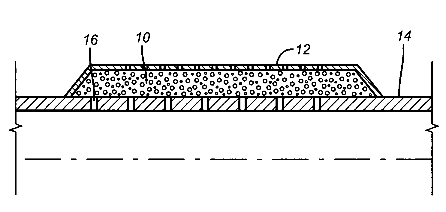
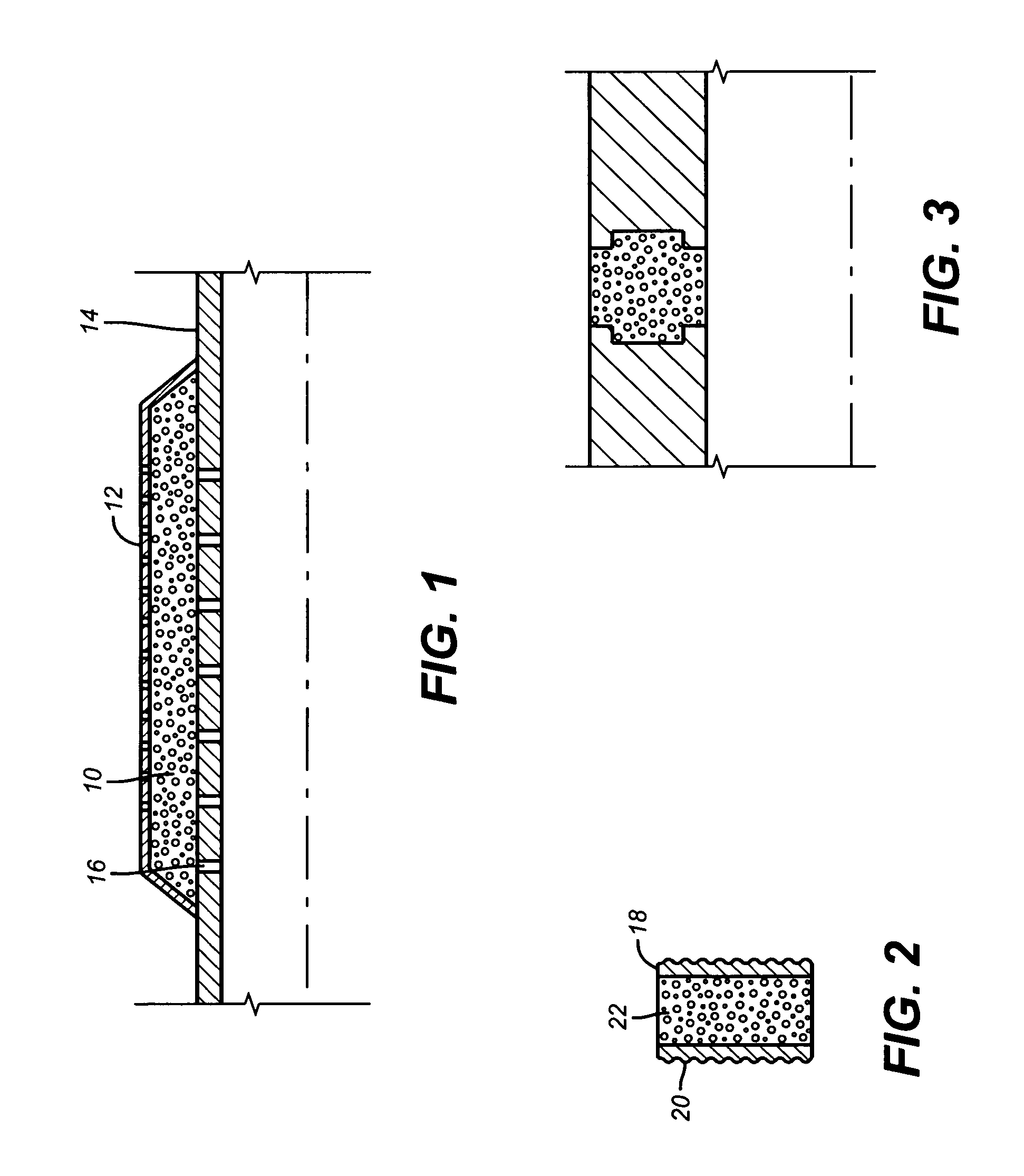
[0009]A method of making porous shapes from unit structures such as beads involves coating the beads with two or more layers of material deposited such that it forms an energetic material. These bi-layer energetic materials are formed from a variety of materials including, but not limited to: Ti & B, Zr & B, Hf & B, Ti & C, Zr & C, Hf & C, Ti & Si, Zr & Si, Nb & Si, Ni & Al, Zr & Al, or Pd & Al, all of which can be deposited from vapor. Pressure is applied to prevent the components from moving and the solid-state reaction between the alternating layers produces exothermic heat. Heat from the reaction alone or in conjunction of an applied brazing compound joins the beads forming a porous shape that is desired. The reaction in the materials may be activated with a small pulse of local energy that can be applied using optical, electrical, or thermal sources. Common examples include an electrical pulse, spark, hot filament, a laser beam, etc. The method reduces energy consumption and the need for specialized equipment. The reactive materials and optional brazing material are preferably applied in a fluidized CVD furnace.

Problems solved by technology

This process required specialized equipment and high energy consumption.

Method used


Image

  • Bead pack brazing with energetics
  • Bead pack brazing with energetics

Examples


Embodiment Construction

[0013]A method of making porous shapes from unit structures such as beads involves coating the beads with two or more layers of material deposited such that it forms an energetic material. These bi-layer energetic materials are formed from a variety of materials including, but not limited to: Ti & B, Zr & B, Hf & B, Ti & C, Zr & C, Hf & C, Ti & Si, Zr & Si, Nb & Si, Ni & Al, Zr & Al, or Pd & Al, all of which can be deposited from vapor. Pressure is applied to prevent the components from moving and the solid-state reaction between the alternating layers produces exothermic heat. Heat from the reaction alone or in conjunction of an applied brazing compound joins the beads forming a porous shape that is desired. In the case of the present invention the combination of the material with objects such as beads generally made of a metallic or other fusible material allows the exothermic reaction that ensues to join or fuse the beads which can be spherical or other regular or irregular shape...


PUM

PropertyMeasurementUnit
shapeaaaaaaaaaa
energyaaaaaaaaaa
shapesaaaaaaaaaa

Abstract

A method of making porous shapes from unit structures such as beads involves coating the beads with two or more layers of material deposited such that it forms an energetic material. These bi-layer energetic materials are formed from a variety of materials including, but not limited to: Ti & B, Zr & B, Hf & B, Ti & C, Zr & C, Hf & C, Ti & Si, Zr & Si, Nb & Si, Ni & Al, Zr & Al, or Pd & Al, all of which can be deposited from vapor. Pressure is applied to prevent the components from moving and the solid-state reaction between the alternating layers produces exothermic heat. Heat from the reaction alone or in conjunction of an applied brazing compound joins the beads forming a porous shape that is desired. The reaction in the materials may be activated with a small pulse of local energy that can be applied using optical, electrical, or thermal sources. Common examples include an electrical pulse, spark, hot filament, a laser beam, etc. The method reduces energy consumption and the need for specialized equipment. The reactive materials and optional brazing material are preferably applied in a fluidized CVD furnace.

Description

FIELD OF THE INVENTION[0001]The field of this invention relates to methods of manufacturing porous aggregate shapes using unit structures that are attached to each other.BACKGROUND OF THE INVENTION[0002]Porous shapes are used in a variety of downhole applications such as for sand control in screens. Such screens are called prepacked screens because they are provided with such porous shapes integrated into a screen assembly. In some cases the presence of the porous material is a substitute for gravel packing the screens downhole. The porous shapes generally involve unitary shapes such as beads to be joined together to form a desired shape.[0003]The way these shapes were made on the past was to coat the beads with a brazing material and feel the beads into a container that represents the desired aggregate shape. That assembly was in turn put into a vacuum furnace and heated while under mechanical compression. This process required specialized equipment and high energy consumption. Acc...

Claims


Application Information

Patent Timeline
Patent Type & Authority Patents(United States)
IPC IPC(8): B23K31/02
CPCB23K1/0008E21B43/082
Inventor HOLMES, KEVIN C.O'BRIEN, ROBERT S.
Owner BAKER HUGHES INC
Learn More